


Power Quality Improvement Using Switch Mode Regulator
#switch mode regulator
#AC voltage regulator
#SCR
#power quality
#voltage waveform
#diode bridge
#phase controlled
#input voltage
#output voltage
#current quality
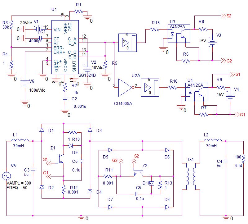
Description: Phase-controlled AC voltage regulator using back-to-back SCRs and diodes, inverse parallel SCRs, and diode-bridge with a single SCR. Input and output voltage waveforms are provided for an input of 250V and an output of 300V. V1 (V5) represents the input voltage in the bottom figure, while V(R14:2) represents the output voltage in the top figure. Power quality refers to the quality of voltage and current, which is crucial in industrial and commercial applications. Common power quality issues include transients, sags, swells, surges, outages, harmonics, and impulses. Voltage sags, in particular, can significantly impact industrial productivity and are often caused by faults in transmission and distribution systems, heavy loads, or switching operations. Both momentary and prolonged voltage sags can lead to equipment failure, overheating, and shutdowns. Solutions such as tap-changing transformers with silicon-controlled rectifiers (SCRs) are typically employed to address continuous voltage sags but lack the capability to adjust to momentary fluctuations. Various power semiconductor devices are currently utilized to enhance power quality. Several AC voltage regulators have been evaluated as solutions for voltage sags, but issues such as non-sinusoidal input currents, low efficiency, and poor power factors have been identified in existing studies. Dynamic Voltage Restorers (DVRs) are sometimes used to stabilize load-side voltage, relying on energy storage devices like flywheels, batteries, and supercapacitors, which can limit their effectiveness in high-power applications. In contrast, switching regulators do not require energy storage devices, making them suitable for both low and high-power applications. This chapter aims to describe the operation and design procedures for a switch-mode AC voltage regulator, beginning with a review of existing regulators and progressing to a step-by-step design and analysis of a switch-mode regulator. The simulation software used for analysis is OrCAD version 9.1. The proposed regulator comprises two main components: a power circuit and a control circuit. The power circuit features two bi-directional switches that provide a freewheeling path for each other. A signal-generating control circuit, utilizing a commercially available pulse width modulator IC chip SG1524B, is integrated with the power circuit to generate switch pulses, resulting in a compact and efficient design. The switching-mode power supply (SMPS) operates at high frequencies, enabling both step-down and step-up voltage conversion.
The phase-controlled AC voltage regulator is designed to manage voltage levels effectively, ensuring that the output voltage remains stable despite fluctuations in the input voltage. The use of back-to-back SCRs allows for bidirectional control of the AC waveform, which is essential for maintaining the desired output voltage. The inclusion of diodes in the circuit aids in protecting the SCRs from reverse voltage conditions, enhancing the overall reliability of the system.
The control circuit plays a pivotal role in the operation of the regulator. By employing a pulse width modulation (PWM) technique, the SG1524B IC chip generates control signals that dictate the timing of the SCRs' conduction. This method allows for precise control over the output voltage, adapting to changes in load conditions and input voltage variations. The high-frequency operation of the SMPS minimizes energy losses and improves efficiency, making it suitable for a wide range of applications.
In terms of performance, the regulator is expected to mitigate common power quality issues, particularly voltage sags, by rapidly adjusting the output voltage in response to disturbances. The design also considers factors such as thermal management and component ratings to ensure that the system can operate reliably under varying load conditions. Overall, the switch-mode AC voltage regulator presents a modern solution to voltage regulation challenges in industrial and commercial settings, combining advanced semiconductor technology with efficient control strategies.Phase controlled AC voltage regulator, (a) Using back to back SCR and diode and (b) using inverse parallel SCR (c) Using diode-bridge and single SCR Figure 30. Input and output voltage waveforms for input 250V and output 300V. V1(V5): Input voltage- bottom figure, V(R14:2): Output voltage top figure. Power quality describes the quality of voltage and current. It is an important consideration in industries and commercial applications. Power quality problems commonly faced are transients, sags, swells, surges, outages, harmonics and impulses [ 1 ]. Among these voltage sags and extended under voltages have large negative impact on industrial productivity, and could be the most important type of power quality variation for many industrial and commercial customers [ 1 - 5 ].
Voltage sags is mainly due to the fault occurring in the transmission and distribution system, loads like welding and operation of building construction equipment, switching of the loaded feeders or equipments. Both momentary and continuous voltage sags are undesirable in complex process controls and household appliances as they use precision electronic and computerized control.
Major problems associated with the unregulated long term voltage sags include equipment failure, overheating and complete shutdown. Tap changing transformers with silicon-controlled rectifiers (SCR) are usually used as a solution of continuous voltage sags [ 6 ].
They require large transformer with many SCRs to control the voltage at the load which lacks the facility of adjusting to momentary changes. Some solutions have been suggested in the past to encounter the problems of voltage sag [ 7 - 11 ]. But these proposals have not been realized practically to replace conventional tap changing transformers.
Now a day`s various power semiconductor devices are used to raise power quality levels to meet the requirements [ 12 ]. Several AC voltage regulators have been studied as a solution of voltage sags [ 13 - 18 ]. In [ 13 ] the input current was not sinusoidal, in [ 14 - 16 ] the efficiency of the regulator was not analyzed and in [ 17 - 18 ] the input power factor was very low and the efficiency is also found poor.
Compact and fully electronic voltage regulators are still unavailable practically. Dynamic Voltage Restorer (DVR) is sometimes used to regulate the load side voltage [ 19 - 21 ]. The DVR requires energy storage device to compensate the voltage sags. Flywheels, batteries, superconducting magnetic energy storage (SMES) and super capacitors are generally used as energy storage devices. The rated power operation of DVR depends on the size and capacity of energy storage device which limits its use in high power applications.
Whereas, switching regulator needs no energy storage devices, therefore, can be used both in low power and high power applications. The objective of this chapter is to describe the operation and design procedure of a switch mode AC voltage regulator.
Firstly, some reviews of the regulators are presented then the procedure of design and analysis of a switch mode regulator is described step by step. Simulation software OrCAD version 9. 1 [ 22 ] is used to analyze the regulator. The proposed regulator consists mainly two parts, power circuit and control circuit. The power circuit consist two bi-directional switches which serve as the freewheeling path for each other.
A signal generating control circuit is to be associated with the power circuit for getting pulses of the switches. In the control circuit, a commercially available pulse width modulator IC chip SG1524B is used, thus circuit is compact and more viable.
A switching-mode power supply (SMPS) is switched at very high frequency. Conversion of both step down and ste
The phase-controlled AC voltage regulator is designed to manage voltage levels effectively, ensuring that the output voltage remains stable despite fluctuations in the input voltage. The use of back-to-back SCRs allows for bidirectional control of the AC waveform, which is essential for maintaining the desired output voltage. The inclusion of diodes in the circuit aids in protecting the SCRs from reverse voltage conditions, enhancing the overall reliability of the system.
The control circuit plays a pivotal role in the operation of the regulator. By employing a pulse width modulation (PWM) technique, the SG1524B IC chip generates control signals that dictate the timing of the SCRs' conduction. This method allows for precise control over the output voltage, adapting to changes in load conditions and input voltage variations. The high-frequency operation of the SMPS minimizes energy losses and improves efficiency, making it suitable for a wide range of applications.
In terms of performance, the regulator is expected to mitigate common power quality issues, particularly voltage sags, by rapidly adjusting the output voltage in response to disturbances. The design also considers factors such as thermal management and component ratings to ensure that the system can operate reliably under varying load conditions. Overall, the switch-mode AC voltage regulator presents a modern solution to voltage regulation challenges in industrial and commercial settings, combining advanced semiconductor technology with efficient control strategies.Phase controlled AC voltage regulator, (a) Using back to back SCR and diode and (b) using inverse parallel SCR (c) Using diode-bridge and single SCR Figure 30. Input and output voltage waveforms for input 250V and output 300V. V1(V5): Input voltage- bottom figure, V(R14:2): Output voltage top figure. Power quality describes the quality of voltage and current. It is an important consideration in industries and commercial applications. Power quality problems commonly faced are transients, sags, swells, surges, outages, harmonics and impulses [ 1 ]. Among these voltage sags and extended under voltages have large negative impact on industrial productivity, and could be the most important type of power quality variation for many industrial and commercial customers [ 1 - 5 ].
Voltage sags is mainly due to the fault occurring in the transmission and distribution system, loads like welding and operation of building construction equipment, switching of the loaded feeders or equipments. Both momentary and continuous voltage sags are undesirable in complex process controls and household appliances as they use precision electronic and computerized control.
Major problems associated with the unregulated long term voltage sags include equipment failure, overheating and complete shutdown. Tap changing transformers with silicon-controlled rectifiers (SCR) are usually used as a solution of continuous voltage sags [ 6 ].
They require large transformer with many SCRs to control the voltage at the load which lacks the facility of adjusting to momentary changes. Some solutions have been suggested in the past to encounter the problems of voltage sag [ 7 - 11 ]. But these proposals have not been realized practically to replace conventional tap changing transformers.
Now a day`s various power semiconductor devices are used to raise power quality levels to meet the requirements [ 12 ]. Several AC voltage regulators have been studied as a solution of voltage sags [ 13 - 18 ]. In [ 13 ] the input current was not sinusoidal, in [ 14 - 16 ] the efficiency of the regulator was not analyzed and in [ 17 - 18 ] the input power factor was very low and the efficiency is also found poor.
Compact and fully electronic voltage regulators are still unavailable practically. Dynamic Voltage Restorer (DVR) is sometimes used to regulate the load side voltage [ 19 - 21 ]. The DVR requires energy storage device to compensate the voltage sags. Flywheels, batteries, superconducting magnetic energy storage (SMES) and super capacitors are generally used as energy storage devices. The rated power operation of DVR depends on the size and capacity of energy storage device which limits its use in high power applications.
Whereas, switching regulator needs no energy storage devices, therefore, can be used both in low power and high power applications. The objective of this chapter is to describe the operation and design procedure of a switch mode AC voltage regulator.
Firstly, some reviews of the regulators are presented then the procedure of design and analysis of a switch mode regulator is described step by step. Simulation software OrCAD version 9. 1 [ 22 ] is used to analyze the regulator. The proposed regulator consists mainly two parts, power circuit and control circuit. The power circuit consist two bi-directional switches which serve as the freewheeling path for each other.
A signal generating control circuit is to be associated with the power circuit for getting pulses of the switches. In the control circuit, a commercially available pulse width modulator IC chip SG1524B is used, thus circuit is compact and more viable.
A switching-mode power supply (SMPS) is switched at very high frequency. Conversion of both step down and ste
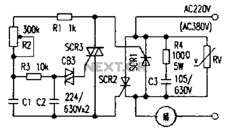
Simple and practical power SCR trigger circuit diagram
The presentation of a general power thyristor trigger circuit is more complex, and some components are difficult to procure. A successful trigger circuit has been constructed for only a few dollars. This circuit is designed to trigger a thyristor module...
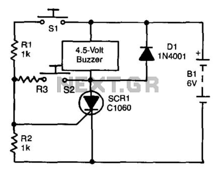
Scr Circuit With Self-Interrupting Load
A self-interrupting device connected to a voltage source operates as a switch that continuously opens and closes; thus, the circuit does not latch in the conventional manner, allowing the alarm to function only while switch SI is closed. Due to...
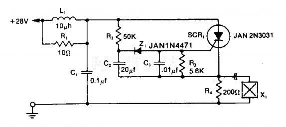
Squib-firing circuit 2
The LRC input network limits the anode dv/dt to a safe value below 30 V/μs. Rl provides critical damping to prevent voltage overshoot. While a simple RC filter section could be used, the high current required by the squib would...
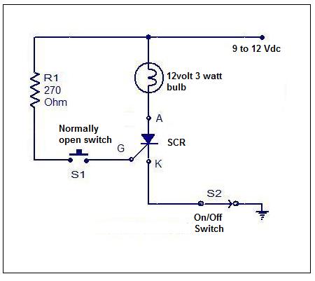
scr tester
Although SCRs and TRIACs are not present in all electronic equipment, they are significant components. Understanding how to test them is essential for troubleshooting. Testing these components can be done with meters, but using an SCR/TRIAC tester is generally easier...
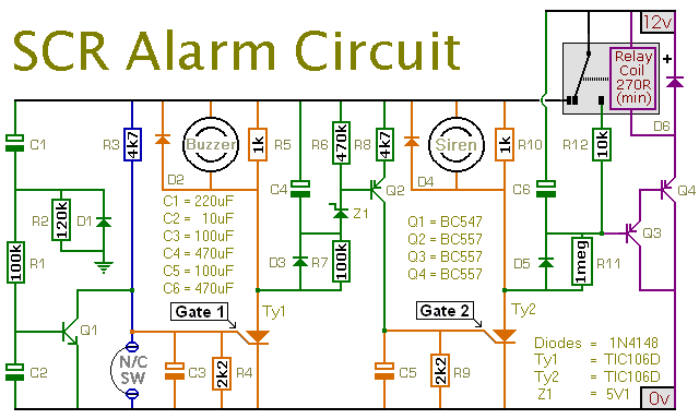
An SCR Based Burglar Alarm
This is a simple SCR-based burglar alarm circuit. Its features include automatic exit and entry delays, along with a timed bell cut-off and reset. It is designed to be used with the usual types of normally-closed input devices such as...
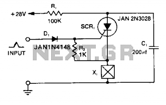
Squib-firing circuit
Capacitor C1 is charged to +28 V through resistor R1 and stores energy for firing the squib. A positive pulse of 1 mA applied to the gate of SCR1 will cause it to conduct, discharging C1 into the squib load...
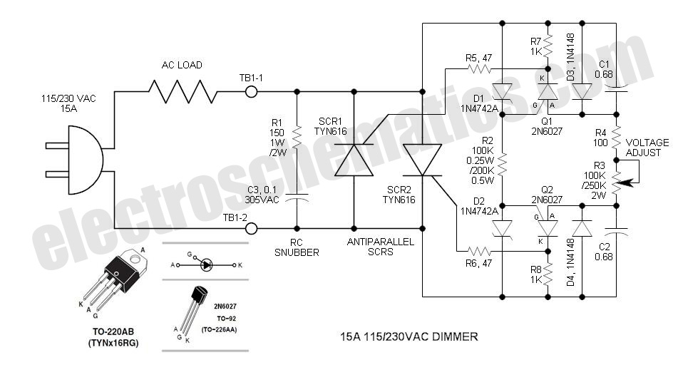
SCR Phase Control Speed Control/Dimmer
The DIAC is a 28V bidirectional trigger device commonly used in inexpensive phase control applications. Its trigger voltage is relatively high for 115VAC phase control. In the past, a similar low voltage trigger device known as a Shockley diode existed,...
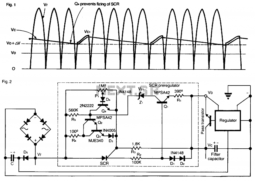
Preregulator for power supply
This SCR pre-regulator maintains the filter capacitor voltage (Vc) in a variable output power supply at a few volts above the output voltage (V0). The advantages include reduced heat dissipation by the pass transistor, resulting in a smaller heatsink, cooler...
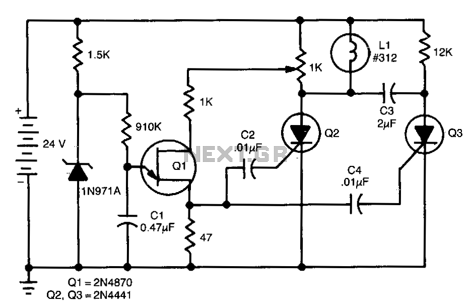
Scr-flasher
This de-flasher utilizes two SCRs and a unijunction oscillator clock to establish the flash rate, which can be adjusted by modifying the value of C1.
The circuit described operates as a de-flasher, a device commonly used in lighting applications to...