


Single-ended regulator
#single-ended
#regulator
#SG1524
#duty-cycle
#modulation
#power supply
#voltage control
#parallel connection
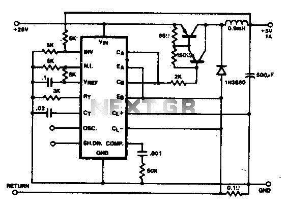
Description: In this conventional single-ended regulator circuit, the two outputs of the SG1524 are connected in parallel for effective 0-90% duty-cycle modulation. The use of an output inductor requires an RC phase compensation network for loop stability.
The described circuit utilizes the SG1524, a versatile pulse-width modulation (PWM) controller, to achieve efficient voltage regulation. By connecting the two outputs of the SG1524 in parallel, the circuit is capable of modulating the duty cycle from 0% to 90%, allowing for a wide range of output voltage adjustments. This modulation is critical in applications where precise voltage levels are required, such as in power supplies for sensitive electronic devices.
The inclusion of an output inductor is essential for energy storage and smoothing the output voltage. The inductor works in conjunction with the output capacitor to filter the PWM signal, resulting in a more stable and less rippled output voltage. However, the presence of the inductor introduces phase shifts in the feedback loop, which can lead to instability if not properly compensated.
To ensure loop stability, an RC phase compensation network is implemented. This network typically consists of a resistor (R) and a capacitor (C) connected in a specific configuration to adjust the phase response of the feedback loop. The resistor is placed in series with the feedback path, while the capacitor is connected to ground. This arrangement helps to counteract the phase lag introduced by the inductor, thus enhancing the stability of the regulator circuit.
In summary, the combination of the SG1524's parallel outputs, output inductor, and an RC phase compensation network forms a robust single-ended regulator circuit capable of delivering stable output voltage across a range of duty cycles. Proper design and implementation of these components are crucial for achieving optimal performance and reliability in various electronic applications.In this conventional single-ended regulator circuit, the two outputs of the:SG1524 are connected in parallel for effective 0-90% duty-cycle modulation The use of an output inductor requires an RC phase compensation network for loop stability.
The described circuit utilizes the SG1524, a versatile pulse-width modulation (PWM) controller, to achieve efficient voltage regulation. By connecting the two outputs of the SG1524 in parallel, the circuit is capable of modulating the duty cycle from 0% to 90%, allowing for a wide range of output voltage adjustments. This modulation is critical in applications where precise voltage levels are required, such as in power supplies for sensitive electronic devices.
The inclusion of an output inductor is essential for energy storage and smoothing the output voltage. The inductor works in conjunction with the output capacitor to filter the PWM signal, resulting in a more stable and less rippled output voltage. However, the presence of the inductor introduces phase shifts in the feedback loop, which can lead to instability if not properly compensated.
To ensure loop stability, an RC phase compensation network is implemented. This network typically consists of a resistor (R) and a capacitor (C) connected in a specific configuration to adjust the phase response of the feedback loop. The resistor is placed in series with the feedback path, while the capacitor is connected to ground. This arrangement helps to counteract the phase lag introduced by the inductor, thus enhancing the stability of the regulator circuit.
In summary, the combination of the SG1524's parallel outputs, output inductor, and an RC phase compensation network forms a robust single-ended regulator circuit capable of delivering stable output voltage across a range of duty cycles. Proper design and implementation of these components are crucial for achieving optimal performance and reliability in various electronic applications.In this conventional single-ended regulator circuit, the two outputs of the:SG1524 are connected in parallel for effective 0-90% duty-cycle modulation The use of an output inductor requires an RC phase compensation network for loop stability.
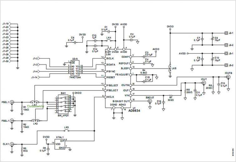
Evaluation Board For The Ad9834 Direct Digital Synthesizer
This document outlines the design of a low-cost 90 W flyback switching power supply intended for use in a multi-sync color monitor. To reduce screen interference caused by switching noise, the power supply can be automatically synchronized to the fixed...
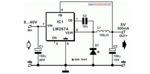
Switch Mode Power Supply
National Semiconductor has been producing and designing integrated circuits (ICs) for use in switch-mode power supplies for many years. The application of these devices is standard.
National Semiconductor has established a significant presence in the design and manufacturing of integrated circuits...
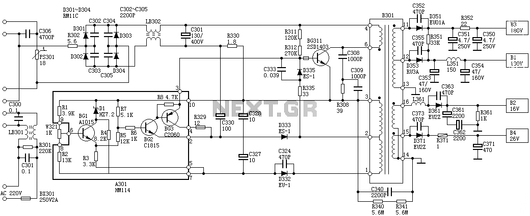
Sanyo 83P switching power supply circuit diagram
Oscillation: The positive terminal voltage of C310 is approximately 300V. The resistors R311 and R312 are connected to the switch BG311 at the B pole, while the B301 winding via the switching transformer (4) and (6) is connected to the...
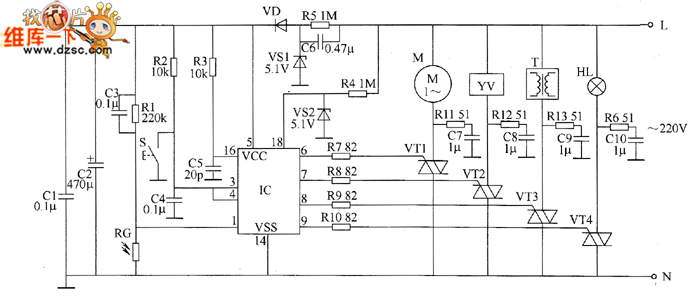
Industrial fuel oil furnace controller circuit diagram 2
The industrial fuel oil furnace controller circuit consists of a power supply circuit, a testing and ignition control circuit, and a control implementation circuit, as illustrated in the accompanying diagram. The power supply circuit includes a step-down capacitor (C6), a...
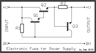
Auto Fuse for power supply
The power supply, with electronic stabilization - mainly those of laboratories - should be protected from overcurrent that emanates from short-circuits, erroneous association, or damage of repaired appliances. The circuit offers effective protection in power supply with output voltage up...
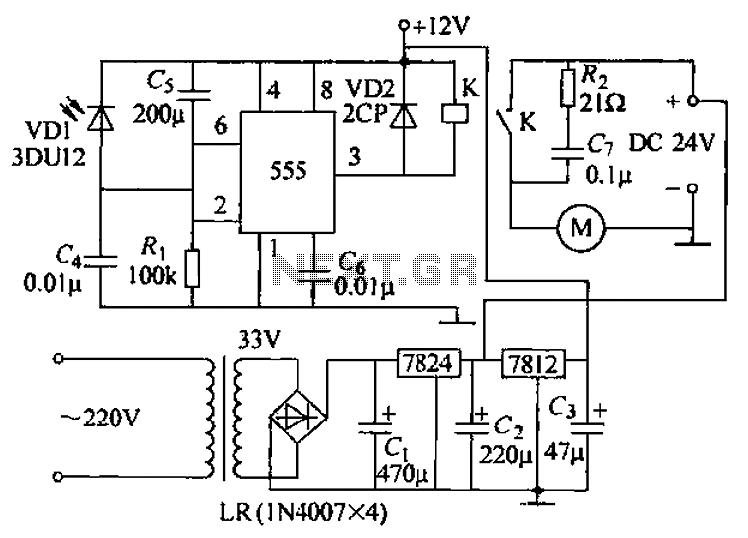
Remote tracking circuit schematics
The circuit consists of two main components: (1) a power supply circuit featuring a transformer (T) that steps down AC 220V to 33V, followed by a full-wave rectifier, a filter, and a three-terminal regulator that outputs +24V. This circuit also...
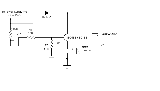
power supply alarm circuit
Most of the power supply failure indicator circuits need a separate power supply for themselves. But the alarm circuit presented here needs no additional supply source. It employs an electrolytic capacitor to store adequate charge, to feed power to the...
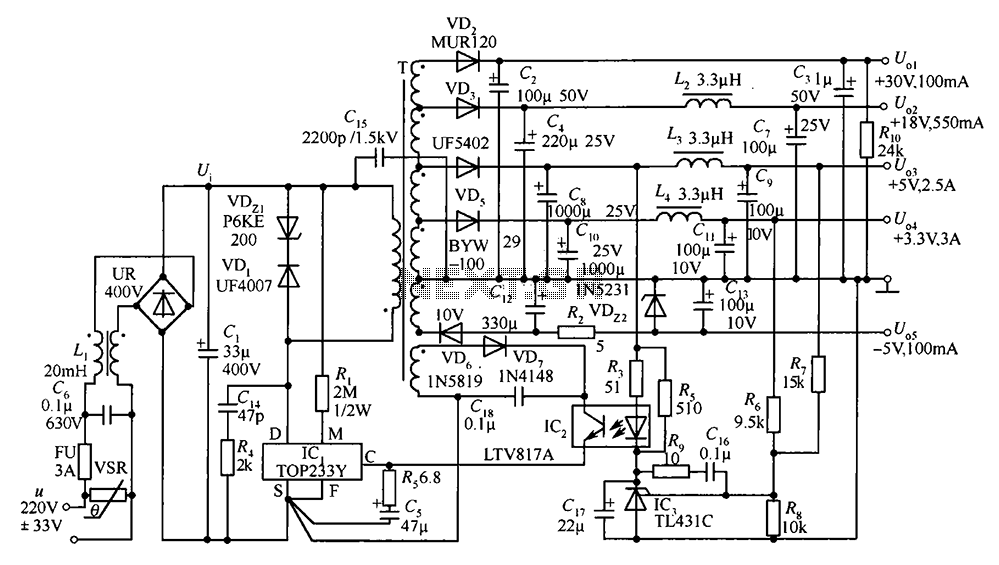
35W switching power supply circuit having a set-top box output of 5
A 35W switching power supply circuit designed for a set-top box output is depicted in Figure 5. It features five distinct voltage outputs: Uo1 (+30V, 100mA), Uo2 (+18V, 550mA), Uo3 (+5V, 2.5A), Uo4 (+3.3V, 3A), and Uo5 (-5V, 100mA). The...
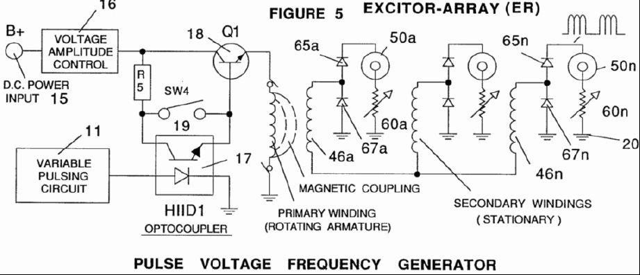
Gas Generator Voltage Control Circuit
A power supply system utilizes a generator as a source of fuel to separate hydrogen and oxygen gases from natural water. It has the capability to control gas production by varying the amplitude of the voltage and/or the pulse repetition...