


Variable Voltage Regulation
#voltage regulation
#variable voltage
#zener diode
#variable resistor
#diode chain
#output control
#regulator
#1N4001
#power supply
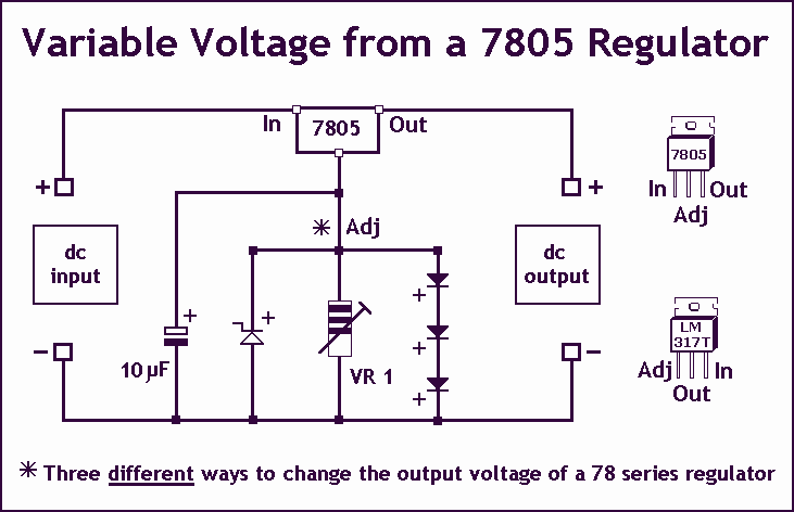
Description: Controlling the output voltage from a regulator can be made variable in three ways:
1. Using a fixed reference zener diode to increase the output by the value of the zener
2. A variable resistor for variable output, note that a voltage less than the nominal regulator is not possible
3. A chain of diode such as 1N4001, this increases the output by +0.7 V for every diode used.
To implement a variable output voltage from a linear voltage regulator, several methods can be employed, each with its own advantages and constraints.
1. **Zener Diode Method**: The use of a fixed reference zener diode is a common approach to increase the output voltage. In this configuration, the zener diode is connected in parallel with the output of the regulator. The breakdown voltage of the zener diode effectively adds to the output voltage of the regulator. For example, if the regulator is set to output 5V and a 3.3V zener diode is used, the total output voltage can be adjusted to approximately 8.3V. It is important to select a zener diode with a power rating that can handle the load current without overheating.
2. **Variable Resistor Method**: A variable resistor, or potentiometer, can be used to adjust the output voltage dynamically. In this setup, the variable resistor is placed in series with the output load. Adjusting the resistance changes the voltage drop across the potentiometer, thus varying the output voltage. However, it should be noted that this method cannot produce an output voltage lower than the nominal output of the regulator, as the minimum output is determined by the regulator's design.
3. **Diode Chain Method**: Another method to increase the output voltage involves using a series of diodes, such as the 1N4001. Each diode introduces a forward voltage drop of approximately 0.7V. By connecting multiple diodes in series with the output of the regulator, the total output voltage can be increased incrementally. For instance, if three diodes are used, the output voltage would be raised by approximately 2.1V. This method is particularly useful for applications where a simple and low-cost solution is required.
Each of these methods provides a means to achieve variable output voltage from a regulator, allowing for flexibility in power supply design. Care should be taken to account for the thermal and electrical characteristics of the components used, as well as the load requirements of the application.Controlling the output voltage from a regulator can be made variable in three ways:- 1. Using a fixed reference zener diode to increase the output by the value of the zener 2. A variable resistor for variable output, note that a voltage less than the nominal regulator is not possible 3. A chain of diode such as 1N4001, this increases the output by +0.7 V for every diode used.
1. Using a fixed reference zener diode to increase the output by the value of the zener
2. A variable resistor for variable output, note that a voltage less than the nominal regulator is not possible
3. A chain of diode such as 1N4001, this increases the output by +0.7 V for every diode used.
To implement a variable output voltage from a linear voltage regulator, several methods can be employed, each with its own advantages and constraints.
1. **Zener Diode Method**: The use of a fixed reference zener diode is a common approach to increase the output voltage. In this configuration, the zener diode is connected in parallel with the output of the regulator. The breakdown voltage of the zener diode effectively adds to the output voltage of the regulator. For example, if the regulator is set to output 5V and a 3.3V zener diode is used, the total output voltage can be adjusted to approximately 8.3V. It is important to select a zener diode with a power rating that can handle the load current without overheating.
2. **Variable Resistor Method**: A variable resistor, or potentiometer, can be used to adjust the output voltage dynamically. In this setup, the variable resistor is placed in series with the output load. Adjusting the resistance changes the voltage drop across the potentiometer, thus varying the output voltage. However, it should be noted that this method cannot produce an output voltage lower than the nominal output of the regulator, as the minimum output is determined by the regulator's design.
3. **Diode Chain Method**: Another method to increase the output voltage involves using a series of diodes, such as the 1N4001. Each diode introduces a forward voltage drop of approximately 0.7V. By connecting multiple diodes in series with the output of the regulator, the total output voltage can be increased incrementally. For instance, if three diodes are used, the output voltage would be raised by approximately 2.1V. This method is particularly useful for applications where a simple and low-cost solution is required.
Each of these methods provides a means to achieve variable output voltage from a regulator, allowing for flexibility in power supply design. Care should be taken to account for the thermal and electrical characteristics of the components used, as well as the load requirements of the application.Controlling the output voltage from a regulator can be made variable in three ways:- 1. Using a fixed reference zener diode to increase the output by the value of the zener 2. A variable resistor for variable output, note that a voltage less than the nominal regulator is not possible 3. A chain of diode such as 1N4001, this increases the output by +0.7 V for every diode used.
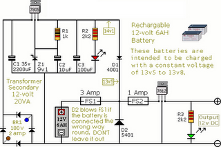
Circuit Diagram Of Alarm Power Supply
The following circuit illustrates an Alarm Power Supply Circuit Diagram. Features include a 1-amp current output, suitable for a Modular Burglar Alarm operating at 12 volts.
The Alarm Power Supply Circuit is designed to provide a stable and reliable power source...
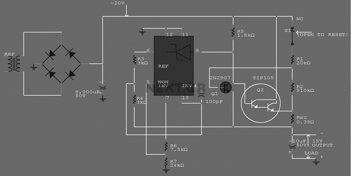
-15 V 1-A Regulated Power Supply
The supply receives -20 V from the rectifier/filter which is fed to the collector of the Darlington pnp pass transistor, a TIP105. The base drive to the TIP105 is supplied through resistor R5. The base of the TIP is driven...
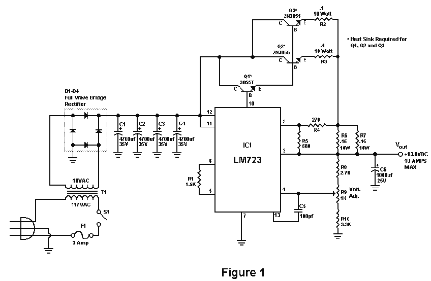
10 Amp 13.8 Volt Power Supply
Sometimes amateurs like to home-brew their power supplies instead of purchasing one off the shelf at any of the major ham radio retail dealers. The advantage to rolling your own power supply is that it teaches us how they work...
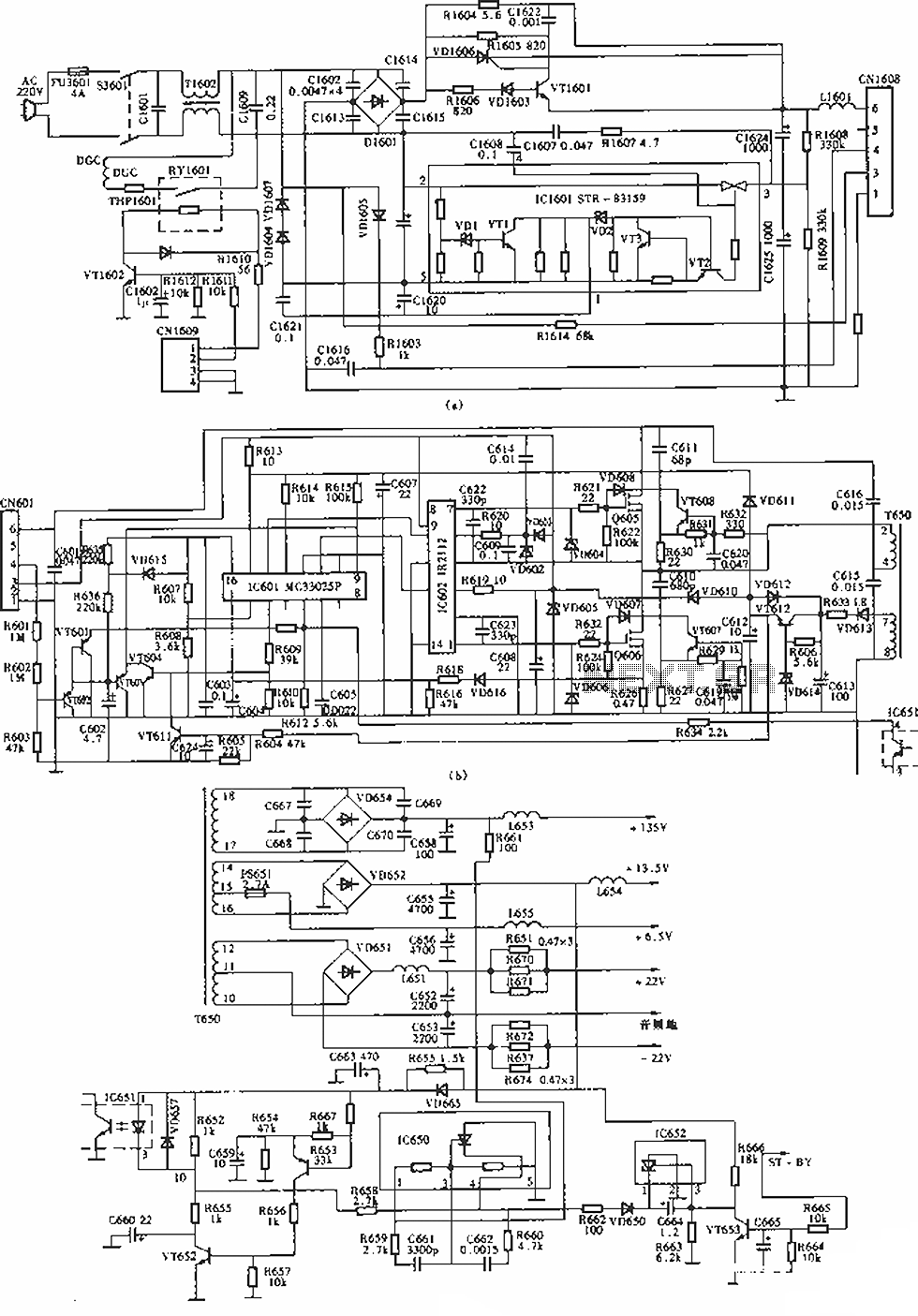
Sony KV-S29MHl TV switching power supply (SIR a 80145A) circuit diagram
The circuit of the Sony KV-S29MHl (S Movement series) TV switching power supply (SIR a 80145A) consists of three main sections: (A) the power oscillation part, (B) the regulator part, and (C) the output section.
The Sony KV-S29MHl TV switching power...

Step-up switching power supply circuit diagram
The design of the power supply circuit diagram utilizes an oscillator circuit from the 74HC series of CMOS logic circuits, with a MOSFET as the switching device. This configuration allows for the development of small-scale power supplies suitable for portable...
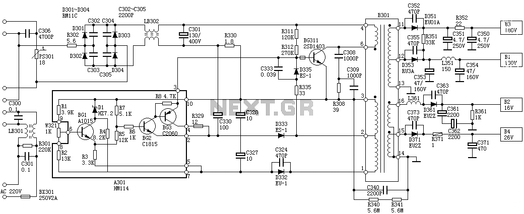
Sanyo 83P switching power supply circuit diagram
Oscillation: The positive terminal voltage of C310 is approximately 300V. The resistors R311 and R312 are connected to the switch BG311 at the B pole, while the B301 winding via the switching transformer (4) and (6) is connected to the...
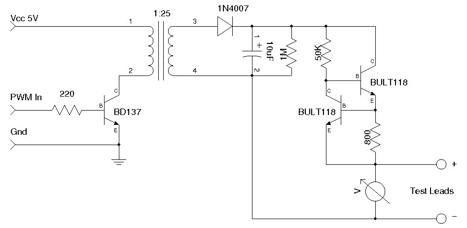
Simple Zener Diode Tester
A simple Zener diode tester circuit, when combined with a PWM generator, can be utilized to measure the breakdown voltage of Zener diodes. More generally, it can also measure the breakdown voltages (e.g., BVceo, BVcbo) of BJTs (Bipolar Junction Transistors)....
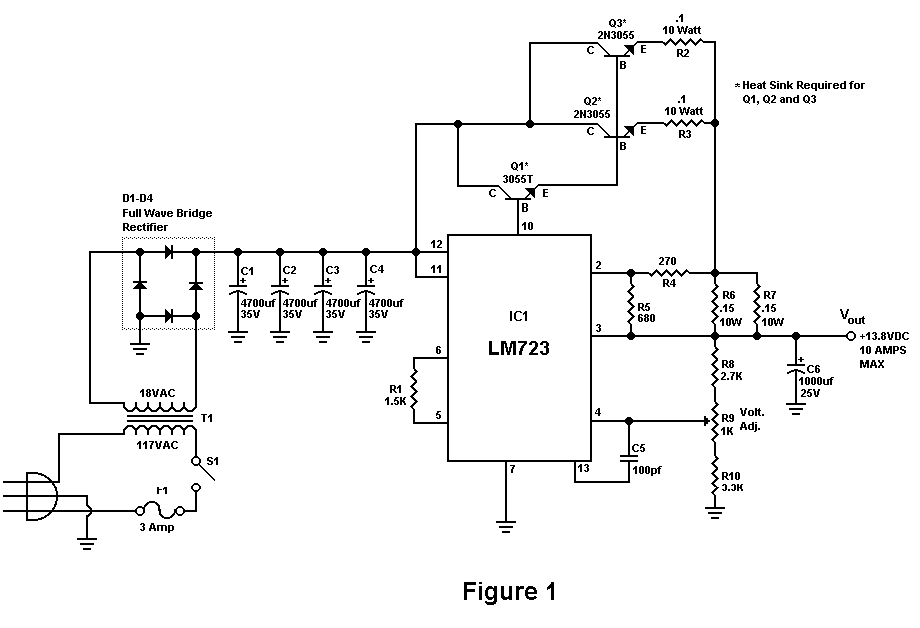
Build A 10 Amp 13.8 Volt Power Supply
Sometimes amateurs like to home-brew their power supplies instead of purchasing one off the shelf at any of the major ham radio retail dealers. The advantage to rolling your own power supply is that it teaches us how they work...
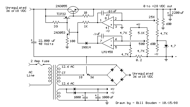
Variable Voltage and Current Power Supply circuit
An alternative approach to utilizing operational amplifiers (op-amps) for power supply regulation is presented. This method necessitates an additional winding on the power transformer to provide the op-amps with a bipolar voltage of +/- 8 volts. The negative voltage generated...