


voltage How to amplify 3.3 volts to 8-9v
#voltage amplification
#PIR sensor
#LED driver
#3.3V to 9V
#boost converter
#motion-activated
#power management
#circuit design
#voltage step-up
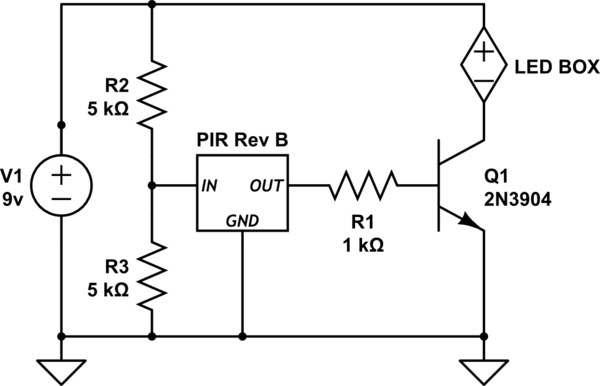
Description: Activate a "black box" of LEDs (operating at 8-9V) when a motion sensor is triggered. The challenge is that the output from the PIR sensor is only 3.3 volts. The schematic provided requires several corrections. Firstly, using a resistor to reduce voltage is not advisable. Additionally, including a model number for the PIR sensor would be beneficial, as well as the current requirements for the LED box. It is important to understand how the LEDs are typically connected to power, such as through a DC wall adapter. Most PIR sensors have outputs that are active for a very short duration per trigger, with a lockout period, which means the LEDs may only illuminate briefly. A common solution is to employ a transistor as a switch, but it is essential to know both the PIR output current and the LED box current for an accurate solution. The Parallax PIR sensor is being used (model available at parallax.com), and the LED box has a current requirement of 8mA (it is a DIY blinking LED kit) that needs to be activated by the PIR sensor. Power will be supplied by a 9V battery.
To design an effective circuit based on the requirements outlined, a transistor can be utilized as a switch to control the LED activation. The Parallax PIR sensor, which outputs a 3.3V signal, will be connected to the base of the transistor. A typical NPN transistor, such as the 2N3904, can be employed for this purpose.
The collector of the transistor will be connected to the LED box, while the emitter will be connected to ground. A pull-down resistor (approximately 10kΩ) should be placed between the base of the transistor and ground to ensure that the transistor remains off when the PIR output is low. To protect the transistor from excessive current, a resistor (typically 1kΩ) should be placed in series with the base.
The LED box, operating at 8-9V and requiring 8mA, will be powered by a 9V battery. The positive terminal of the battery will connect to the anode of the LED box, while the cathode will connect to the collector of the transistor. When the PIR sensor is triggered, it will output a 3.3V signal to the base of the transistor, allowing current to flow from the collector to the emitter, thus illuminating the LED box.
It is crucial to ensure that the transistor can handle the current requirements of the LED box. The specifications of the chosen transistor should be reviewed to confirm it can adequately support the load. Additionally, the PIR sensor's datasheet should be consulted to understand its output current capabilities, ensuring that it can effectively drive the base of the transistor.
This circuit configuration allows for the LEDs to be activated for the duration that the PIR sensor is triggered, providing a practical solution to the initial problem while ensuring that the components are correctly matched to their operational requirements.Turn on a "black box" of leds (that operates at 8-9v) when my motion sensor is activated. The problem I`ve got is that the output of my PIR is only 3. 3 volts. Here is my crappy schematic. There are a few things that need to be fixed. First, A resistor is not a good way to reduce voltage. Second, a model number for the PIR sensor, would be useful. As would the current requirements for the LED box. How are the leds normally connected to power, a dc wallwart/adaptor Most PIR sensors outputs are only on for a very small amount of time per trigger, with a lockout period, so the leds might only be on for a very short time. A generic answer would be using a transistor as a switch, but you need to know the PIR output current and the LED box current for a proper answer.
Passerby Apr 16 `13 at 0:53 Im using the Parallax PIR : parallax. com/tabid/768/productid/83/default. aspx The Led Box current requierement is 8mA (it is a "solder yourself" blinking leds kit) and I just happend to want to turn it on when the PIR sensor is activated. Power will be coming from a 9v battery. Rhyuk Apr 16 `13 at 1:08
To design an effective circuit based on the requirements outlined, a transistor can be utilized as a switch to control the LED activation. The Parallax PIR sensor, which outputs a 3.3V signal, will be connected to the base of the transistor. A typical NPN transistor, such as the 2N3904, can be employed for this purpose.
The collector of the transistor will be connected to the LED box, while the emitter will be connected to ground. A pull-down resistor (approximately 10kΩ) should be placed between the base of the transistor and ground to ensure that the transistor remains off when the PIR output is low. To protect the transistor from excessive current, a resistor (typically 1kΩ) should be placed in series with the base.
The LED box, operating at 8-9V and requiring 8mA, will be powered by a 9V battery. The positive terminal of the battery will connect to the anode of the LED box, while the cathode will connect to the collector of the transistor. When the PIR sensor is triggered, it will output a 3.3V signal to the base of the transistor, allowing current to flow from the collector to the emitter, thus illuminating the LED box.
It is crucial to ensure that the transistor can handle the current requirements of the LED box. The specifications of the chosen transistor should be reviewed to confirm it can adequately support the load. Additionally, the PIR sensor's datasheet should be consulted to understand its output current capabilities, ensuring that it can effectively drive the base of the transistor.
This circuit configuration allows for the LEDs to be activated for the duration that the PIR sensor is triggered, providing a practical solution to the initial problem while ensuring that the components are correctly matched to their operational requirements.Turn on a "black box" of leds (that operates at 8-9v) when my motion sensor is activated. The problem I`ve got is that the output of my PIR is only 3. 3 volts. Here is my crappy schematic. There are a few things that need to be fixed. First, A resistor is not a good way to reduce voltage. Second, a model number for the PIR sensor, would be useful. As would the current requirements for the LED box. How are the leds normally connected to power, a dc wallwart/adaptor Most PIR sensors outputs are only on for a very small amount of time per trigger, with a lockout period, so the leds might only be on for a very short time. A generic answer would be using a transistor as a switch, but you need to know the PIR output current and the LED box current for a proper answer.
Passerby Apr 16 `13 at 0:53 Im using the Parallax PIR : parallax. com/tabid/768/productid/83/default. aspx The Led Box current requierement is 8mA (it is a "solder yourself" blinking leds kit) and I just happend to want to turn it on when the PIR sensor is activated. Power will be coming from a 9v battery. Rhyuk Apr 16 `13 at 1:08
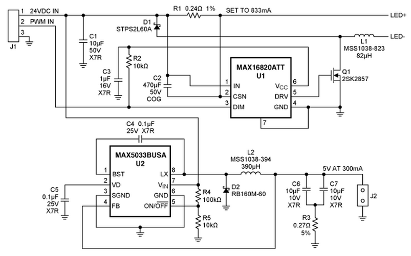
rd mr 16 led driver
A reference design for a 4S1P MR-16 LED driver that provides 750mA to a string of four white LEDs (WLEDs). The circuit operates from a 24V source and is based around the MAX16820 hysteretic LED driver. Also included is a...
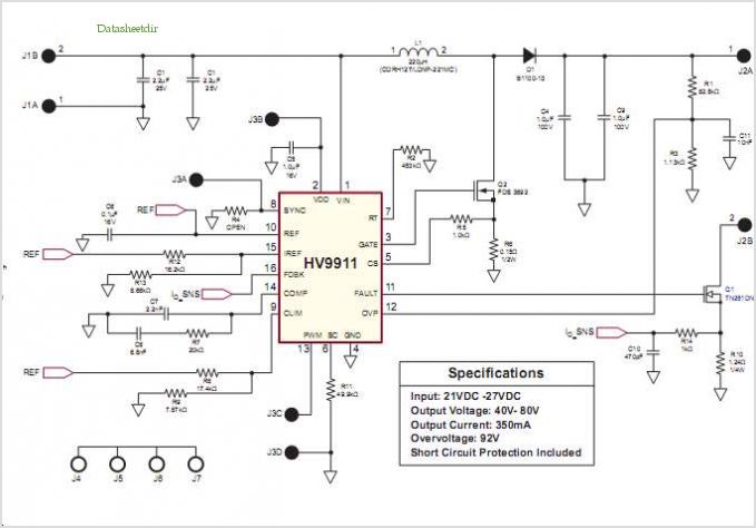
High Brightness Boost Led Driver With 1:3000 Dimming Ratio And Excellent Current Regulation
Conventionally, a MOSFET with a voltage rating of 1500V or a Half-Bridge configuration utilizing two MOSFETs rated at 800-900V is employed for Switch Mode Power Supply (SMPS) applications that require input voltages exceeding 380Vac. However, these methods present challenges, including...
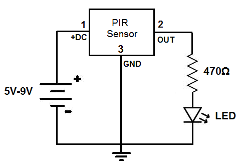
Motion Detector Circuit
This circuit is designed to detect motion or movement, with its most common application being the detection of a person moving through an area covered by the motion detector. The primary electronic component utilized for this detection is the PIR...
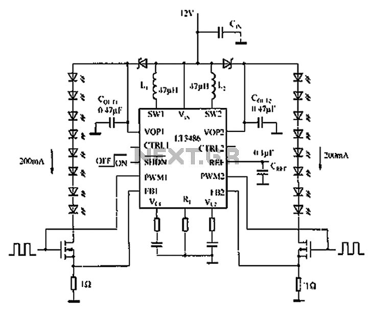
Automotive LED driver circuit diagram LT3486
The automotive LED driver circuit diagram utilizes the LT3486. The LED is employed in the car's central high-mounted stop lamp (CHMSL), providing advantages such as faster achievement of the set brightness, higher efficiency, longer lifespan, and simplified design and installation...
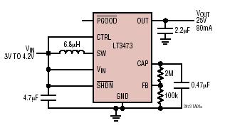
Micropower 1A Boost Converter with Schottky and Output Disconnect
The LT3473 and LT3473A are micropower step-up DC/DC converters that integrate a Schottky diode and output disconnect circuitry within low-profile DFN packages. Their compact size, high integration level, and utilization of small surface-mount technology (SMT) components result in a solution...
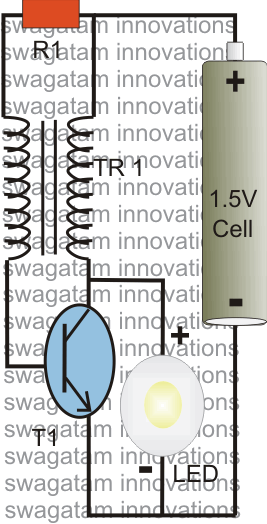
1 watt LED Driver Using a Joule Thief Circuit
The post explains a simple 1 watt LED driver circuit using a single 1.5 V penlight cell through the joule thief concept. The coil may be wound over a T13 toroidal ferrite core using 0.2 mm or 0.3 mm super...
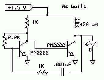
ciruits and chematics
This is the current schematic for the Boost converter. The negative power is connected to the emitters and the LED cathode. With the values shown, the circuit draws approximately 18 mA and drives the LED to around 5 mA. A...
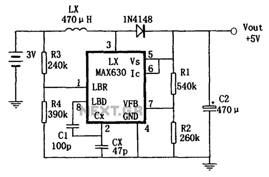
Boost has a frequency characteristic of automatic offset MAX630 power conversion
A low voltage frequency circuit utilizes the MAX630 for low battery voltage detection, functioning as an offset boost converter power supply. It is designed to maintain high efficiency (85%) while providing a DC output voltage of 5V at a current...
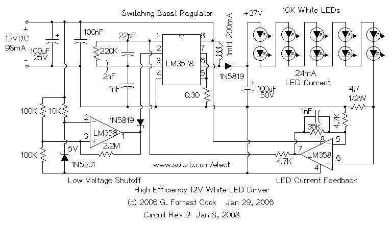
12V White LED Driver
The heart of the circuit is a string of 10 white LEDs. These are wired in series and connected to a current-regulated step-up switching power supply circuit. DC powered LED lighting circuits can vary from the trivial, with a single...