


Based on Bluetooth wireless transmission-reception circuit design schematics
#bluetooth
#wireless transmission
#LC oscillator
#SAW device
#frequency stability
#crystal
#RF
#communication
#transceiver
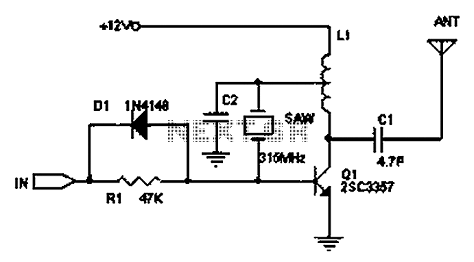
Description: The circuit principle involves the use of an LC oscillator, which typically experiences significant frequency drift. Surface Acoustic Wave (SAW) devices have emerged as a solution to this issue, offering frequency stability comparable to that of crystal oscillators. SAW devices can achieve fundamental frequencies reaching into the hundreds of megahertz or even gigahertz. Unlike crystal oscillators, the circuit design with SAW devices is considerably simpler. The circuit presented is a common transmitter circuit that benefits from the stability provided by SAW devices; thus, even when manipulating the antenna or other components, the transmission frequency remains stable. The effective range is up to 200 meters. A super-regenerative receiver can be implemented, or a superheterodyne circuit may be used. The super-regenerative circuit is characterized by low cost and low power consumption, operating at approximately 100 µA. It allows for adjustments in sensitivity and oscillation levels and can be integrated with a mixer and two similar superheterodyne receivers. However, the operational stability of the super-regenerative circuit is relatively poor, and it exhibits low selectivity, which can lead to increased interference.
The circuit utilizes a SAW device to enhance frequency stability, making it suitable for applications where precise frequency control is essential. The simplicity of the circuit design, compared to traditional crystal oscillators, allows for easier implementation and integration into various systems. The transmitter circuit can be configured to operate at high frequencies, leveraging the capabilities of SAW technology to maintain consistent performance over a range of environmental conditions.
In practical applications, the transmitter can be paired with a super-regenerative receiver, which is advantageous due to its low power requirements and cost-effectiveness. The super-regenerative receiver operates by exploiting the oscillation characteristics of the circuit, which can be fine-tuned for sensitivity based on the specific requirements of the application. Despite its benefits, users must be aware of the trade-offs associated with the super-regenerative design, particularly in terms of selectivity and susceptibility to interference.
For enhanced performance, it may be beneficial to incorporate additional filtering stages or to employ a superheterodyne receiver configuration, which can provide improved stability and selectivity at the expense of increased complexity and cost. This configuration allows for better handling of interference and more precise frequency selection, making it suitable for applications requiring high fidelity and reliability in signal reception. Overall, the integration of SAW devices in this circuit design represents a significant advancement in achieving stable, high-frequency transmission and reception capabilities in electronic communication systems. Circuit Principle: Using LC oscillator frequency drift is more serious. SAW devices appear to solve this problem, the frequency stability of the crystal substantially the same, and its fundamental frequency of up to hundreds of megabytes or even gigahertz. Without octave, compared with the crystal oscillator circuit is extremely simple. The following circuit is a common transmitter circuit, due to the use of SAW devices, the circuit is very stable, even grasping antenna, acoustic or other parts of the circuit, the transmission frequency will not drift. Up to 200 meters, while a super-regenerative receiver may use a circuit or superheterodyne circuit, the super-regenerative circuit low cost, low power consumption of up to 100uA, good super regenerative circuit to adjust the sensitivity level and high level, the oscillation level, placed in a mixer and two similar superheterodyne receiver.
However, job stability super regenerative circuit is relatively poor, poor selectivity, thereby reducing interference.
The circuit utilizes a SAW device to enhance frequency stability, making it suitable for applications where precise frequency control is essential. The simplicity of the circuit design, compared to traditional crystal oscillators, allows for easier implementation and integration into various systems. The transmitter circuit can be configured to operate at high frequencies, leveraging the capabilities of SAW technology to maintain consistent performance over a range of environmental conditions.
In practical applications, the transmitter can be paired with a super-regenerative receiver, which is advantageous due to its low power requirements and cost-effectiveness. The super-regenerative receiver operates by exploiting the oscillation characteristics of the circuit, which can be fine-tuned for sensitivity based on the specific requirements of the application. Despite its benefits, users must be aware of the trade-offs associated with the super-regenerative design, particularly in terms of selectivity and susceptibility to interference.
For enhanced performance, it may be beneficial to incorporate additional filtering stages or to employ a superheterodyne receiver configuration, which can provide improved stability and selectivity at the expense of increased complexity and cost. This configuration allows for better handling of interference and more precise frequency selection, making it suitable for applications requiring high fidelity and reliability in signal reception. Overall, the integration of SAW devices in this circuit design represents a significant advancement in achieving stable, high-frequency transmission and reception capabilities in electronic communication systems. Circuit Principle: Using LC oscillator frequency drift is more serious. SAW devices appear to solve this problem, the frequency stability of the crystal substantially the same, and its fundamental frequency of up to hundreds of megabytes or even gigahertz. Without octave, compared with the crystal oscillator circuit is extremely simple. The following circuit is a common transmitter circuit, due to the use of SAW devices, the circuit is very stable, even grasping antenna, acoustic or other parts of the circuit, the transmission frequency will not drift. Up to 200 meters, while a super-regenerative receiver may use a circuit or superheterodyne circuit, the super-regenerative circuit low cost, low power consumption of up to 100uA, good super regenerative circuit to adjust the sensitivity level and high level, the oscillation level, placed in a mixer and two similar superheterodyne receiver.
However, job stability super regenerative circuit is relatively poor, poor selectivity, thereby reducing interference.
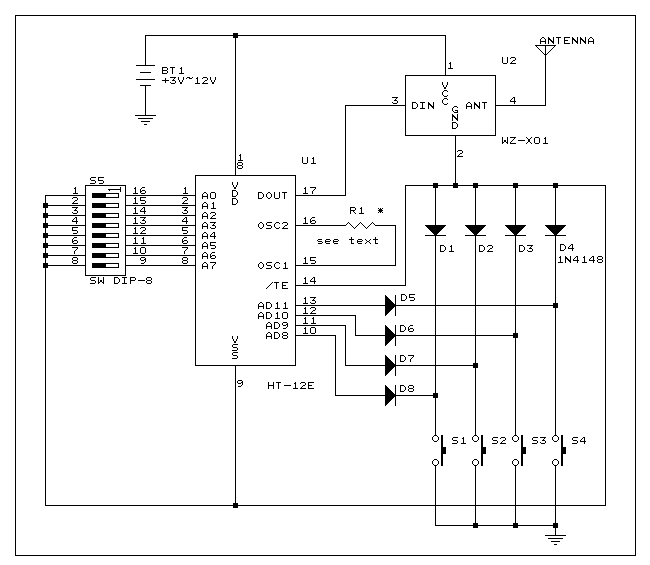
Four channel RF remote control
This is a simple RF transmitter circuit utilizing the Holtek HT-12E encoder chip and an AM 418MHz transmitter module (WZ-X01). The use of hybrid RF transmit/receive modules simplifies the construction of the RF remote control. The transmitter can operate with...
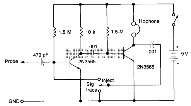
Single injector-tracer
In the "Trace" mode, the non-linear operation of the amplifier will detect modulated RF signals, which will be filtered by the 0.001 µF capacitor and heard in the headphones. In the "Inject" mode, this circuit will provide a nominal square...
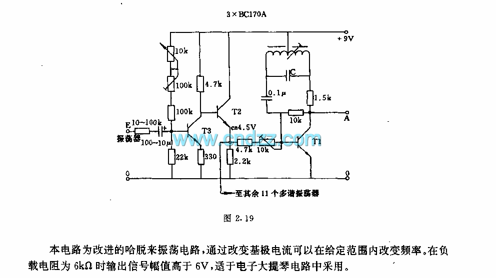
The LC oscillator circuit for electronic cello
This circuit is an enhanced Hartley oscillator, which allows for frequency adjustment within a specified range by altering the base current. The output signal amplitude exceeds 6V when tested with a 6kΩ load resistance, making it suitable for use in...
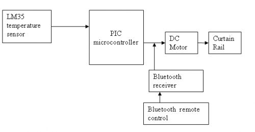
bluetooth curtain system
The circuit is designed for a DC motor and Bluetooth system, where the Bluetooth remote control is utilized to open and close curtains. A block diagram is provided for reference. A mobile phone can be used to develop a J2ME...
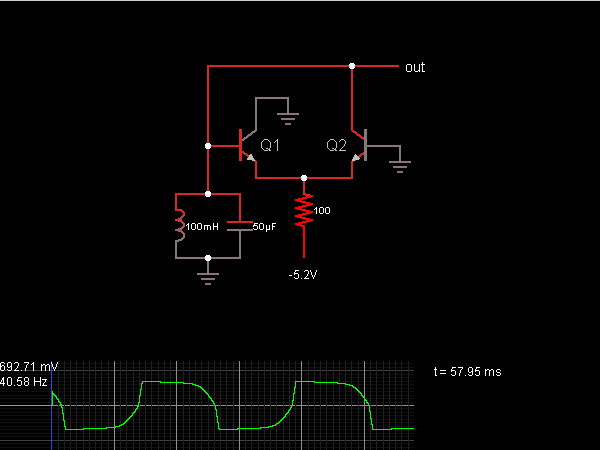
Emitter-Coupled LC Oscillator
When the oscillator starts, Q2 is in a conducting state; the current flows from the capacitor, charging it until the voltage across it is sufficient to allow current to flow through the inductor. As the current through the inductor reaches...
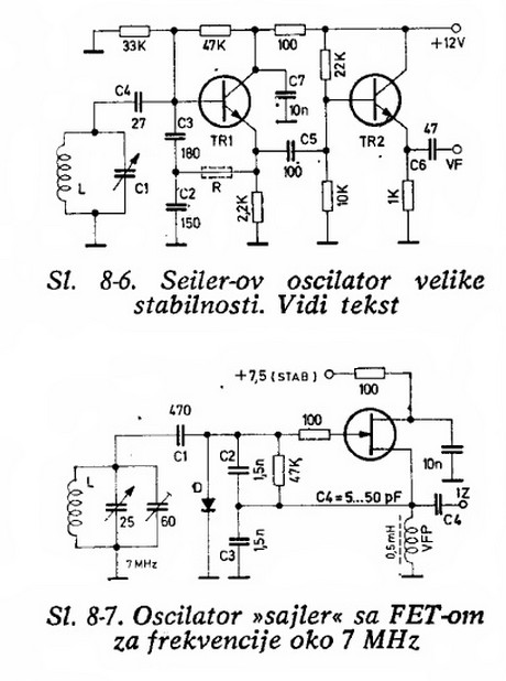
High-stability oscillators (non-crystal)
Will an LC-based oscillator be able to demonstrate performance comparable to crystals under such conditions (possibly in unusual configurations like LC-opamp) so that any energy loss at each stage is recovered, resulting in a narrower bandwidth? Examine some amateur radio...
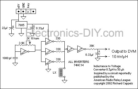
RF Inductance Meter
This RF inductance meter measures RF chokes in the 500 nH to 50 µH range. A simple solution was required to measure hand-wound RF inductors in a secondary lab setting. The user intended to utilize this device occasionally and did...
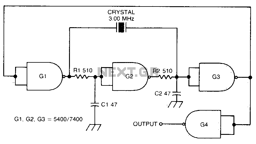
Crystal-controlled oscillator
This circuit oscillates without the crystal. When the crystal is included in the circuit, the frequency will match that of the crystal. The circuit exhibits good starting characteristics even with low-quality crystals.
This circuit design features a basic oscillator configuration that...
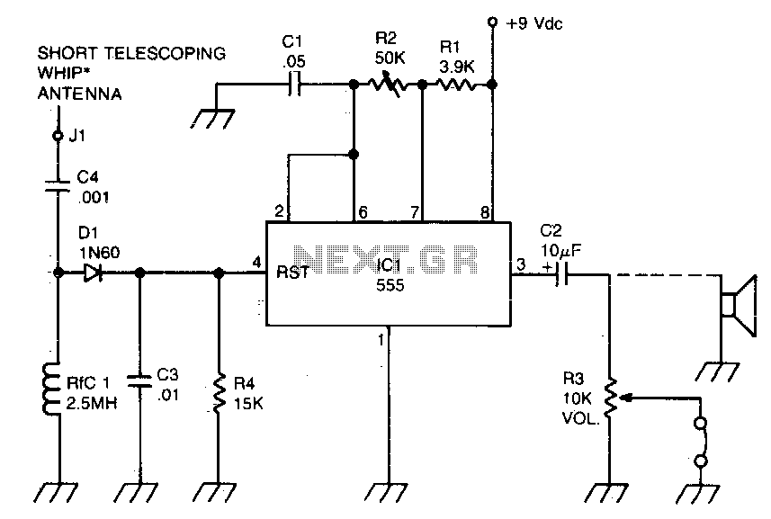
RF-powered sidetone oscillator
A sidetone oscillator is a specific type of audio astable multivibrator. Keying is achieved by turning the oscillator on and off through the application of a positive DC potential, which is generated from the RF signal to the reset terminal...