


NFC Tag communication system
#NFC
#RFID
#antenna circuit
#resonance frequency
#communication
#wireless communication
#tag
#LSI
#resonance capacity
#frequency adjustment

Description: A calculating resonance capacity is derived from formula (1), and an NFC Tag LSI is integrated into the antenna circuit board. The resonance frequency is measured, followed by adjustments to the resonance capacity.
The circuit design involves calculating the resonance capacity using a specific formula, which is essential for optimizing the performance of the NFC (Near Field Communication) system. The NFC Tag LSI, or Large Scale Integration, is a critical component that facilitates communication between the NFC tag and the reader.
The antenna circuit board is designed to support the NFC Tag LSI, ensuring that it can effectively transmit and receive signals. The resonance frequency of the antenna is a crucial parameter that affects the efficiency of the NFC communication. This frequency must be precisely measured to ensure that the antenna operates at its optimal performance level.
After measuring the resonance frequency, adjustments to the resonance capacity are necessary. This adjustment process may involve changing the values of capacitors in the circuit or altering the physical dimensions of the antenna to achieve the desired resonance frequency.
The overall goal of this process is to ensure that the NFC system operates reliably and efficiently, facilitating seamless communication in applications such as mobile payments, access control, and data transfer. Proper tuning of the resonance capacity directly impacts the range and effectiveness of the NFC communication, making it a vital aspect of the circuit design.A calculating resonance capacity from formula (1) and NFC Tag LSI are set to antenna circuit board, and measured resonance frequency, after that, adjusting resonance capacity
The circuit design involves calculating the resonance capacity using a specific formula, which is essential for optimizing the performance of the NFC (Near Field Communication) system. The NFC Tag LSI, or Large Scale Integration, is a critical component that facilitates communication between the NFC tag and the reader.
The antenna circuit board is designed to support the NFC Tag LSI, ensuring that it can effectively transmit and receive signals. The resonance frequency of the antenna is a crucial parameter that affects the efficiency of the NFC communication. This frequency must be precisely measured to ensure that the antenna operates at its optimal performance level.
After measuring the resonance frequency, adjustments to the resonance capacity are necessary. This adjustment process may involve changing the values of capacitors in the circuit or altering the physical dimensions of the antenna to achieve the desired resonance frequency.
The overall goal of this process is to ensure that the NFC system operates reliably and efficiently, facilitating seamless communication in applications such as mobile payments, access control, and data transfer. Proper tuning of the resonance capacity directly impacts the range and effectiveness of the NFC communication, making it a vital aspect of the circuit design.A calculating resonance capacity from formula (1) and NFC Tag LSI are set to antenna circuit board, and measured resonance frequency, after that, adjusting resonance capacity
GlueLogix Technical Services
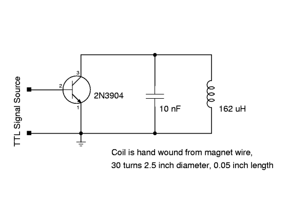
A wireless interface for your next project. With a coil, a capacitor, and a transistor, it is possible to create a device that emulates a Radio Frequency Identification Device (RFID), commonly referred to as a "tag" or "RFID tag." A...
Human-Computer Interface Technology 1
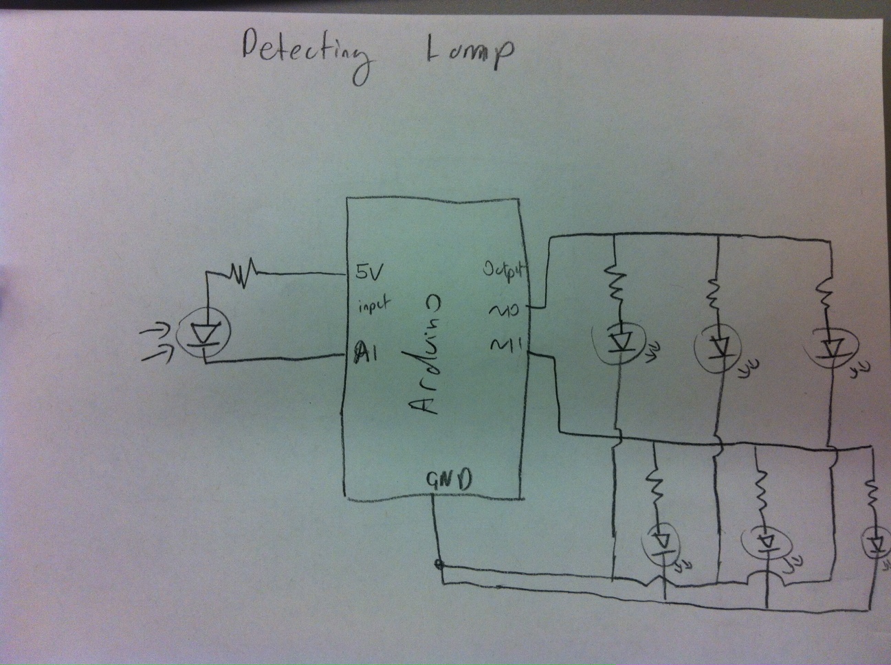
A habit-acquisition system that tags physical objects, such as dumbbells and medicine bottles, with RF tags or microcontrollers to detect and log user interactions with these items. It includes virtual plants and creatures that simulate the health of real-world aspects...
connect 4000
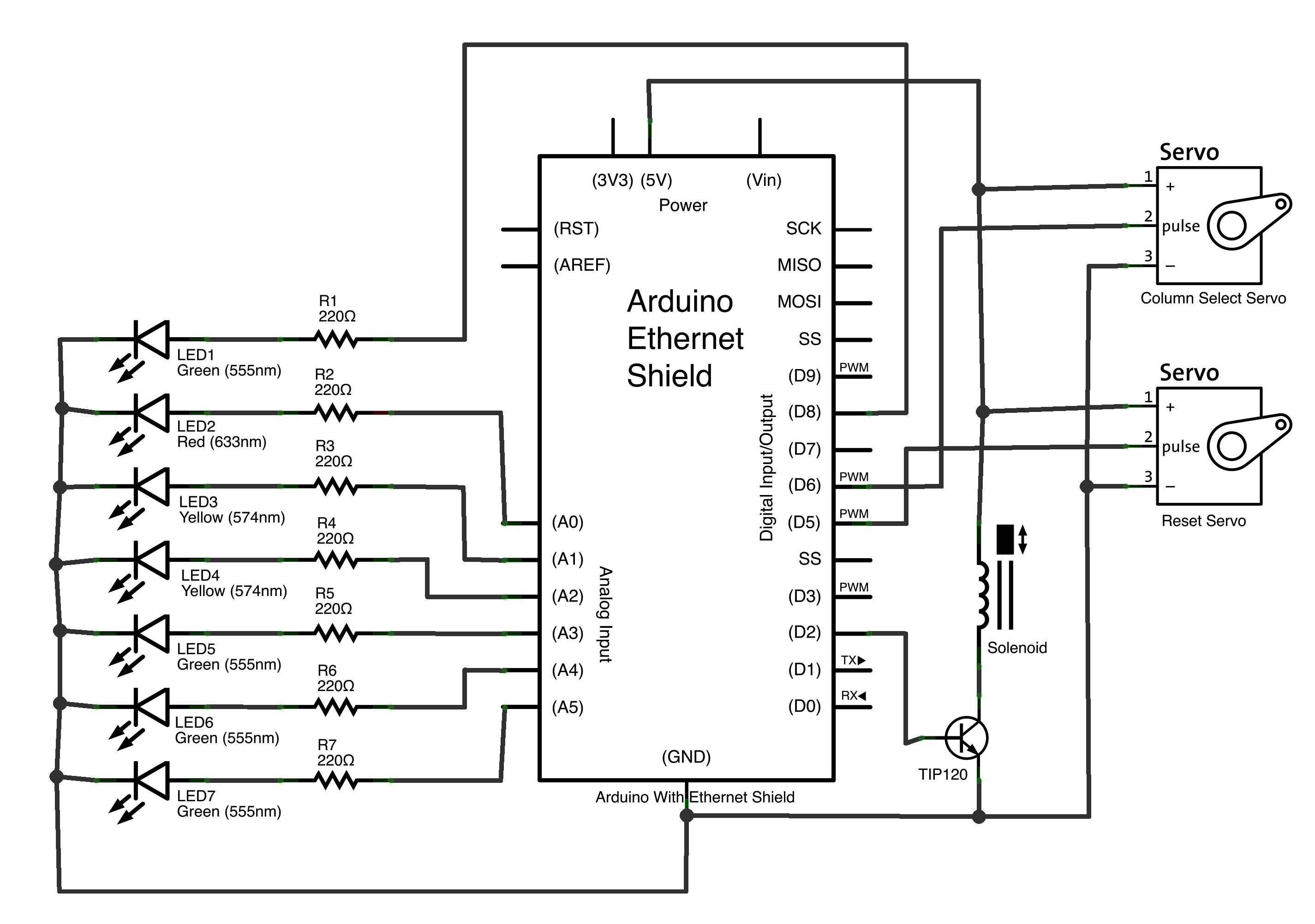
The objective of this project was to investigate the wireless linkage of objects, locations, and individuals. Initial discussions revolved around the intended use of the project—whether for private or public purposes—and the number of participants involved. Considerations included the choice...
DIY FSK RFID Reader using Arduino
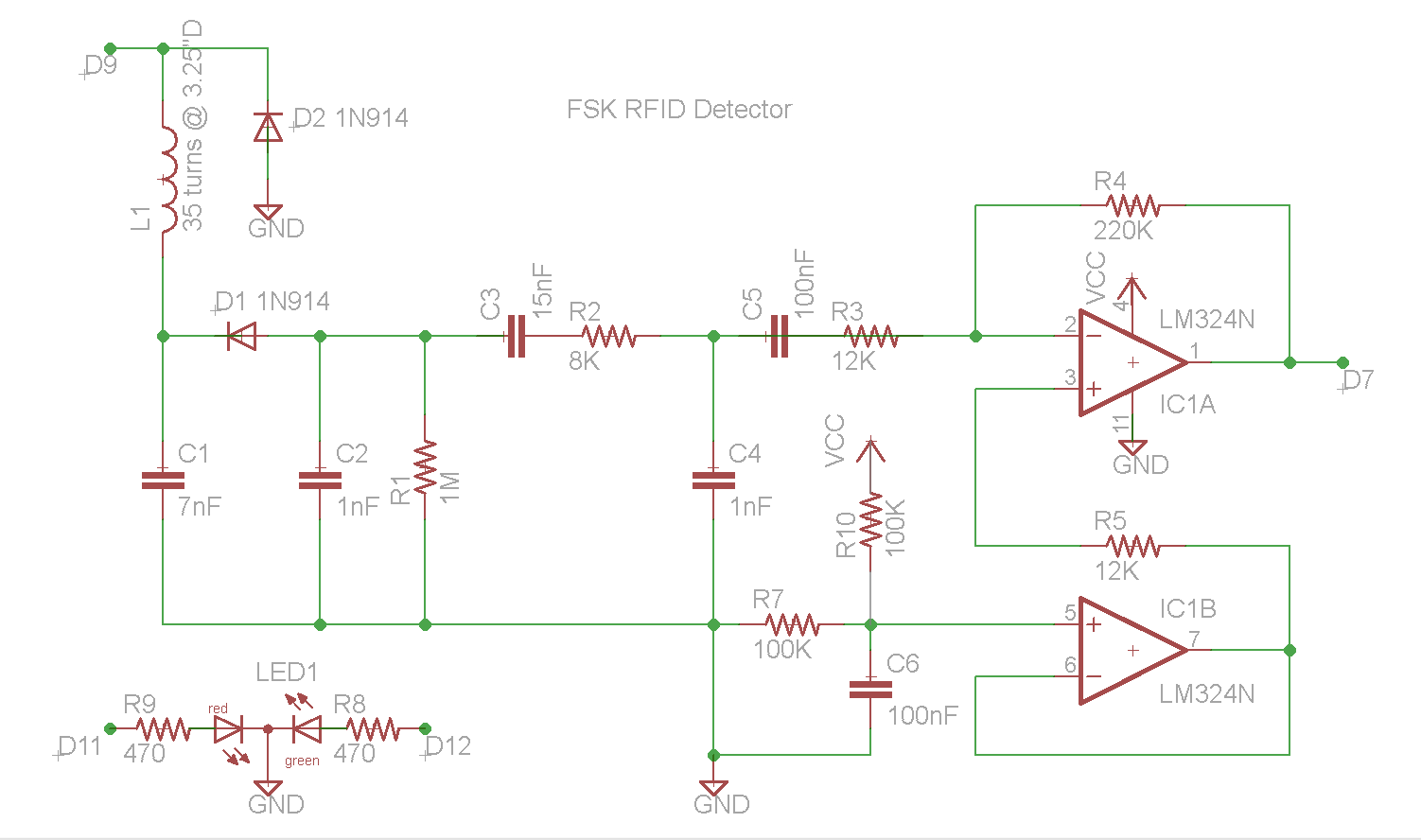
This document describes the construction of an RFID reader utilizing an Arduino (specifically tested with the Nano 3.0, although other models may also be compatible), a hand-wound wire coil, and various low-cost common components. RFID readers are devices manufactured by...
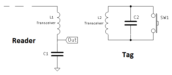
simple rf id reader module design
A coil of approximately 1 mH is utilized for both sides of the circuit. Given a chosen frequency of 125 kHz, the required capacitor value is calculated to be 1.62 nF, with a standard value of 1.5 nF selected. L1...
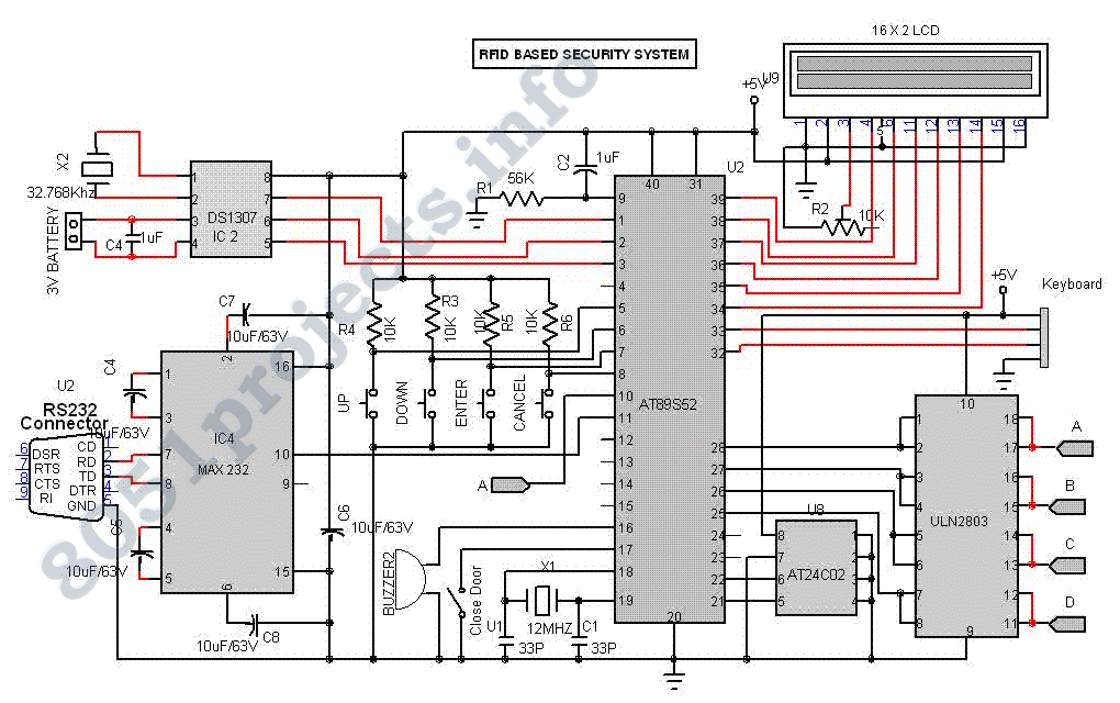
RFID Based Security System with AT89S52
This project aimed to develop a wireless system to detect and allow only the authorized persons. The system was based on Radio Frequency Identification (RFID) technology and consists of a passive RFID tag. The passive micro transponder tag collects power...
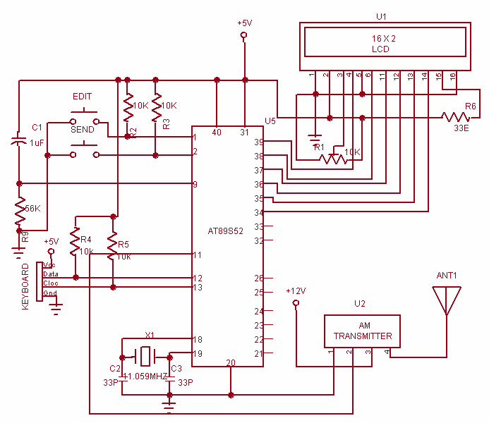
Wireless Data Communication system
This project is used to communicate or transmit a text message from one place to another place through wireless. The text message is encrypted by using the Microcontroller and the encrypted message was transmitted through wireless. At the receiver end...
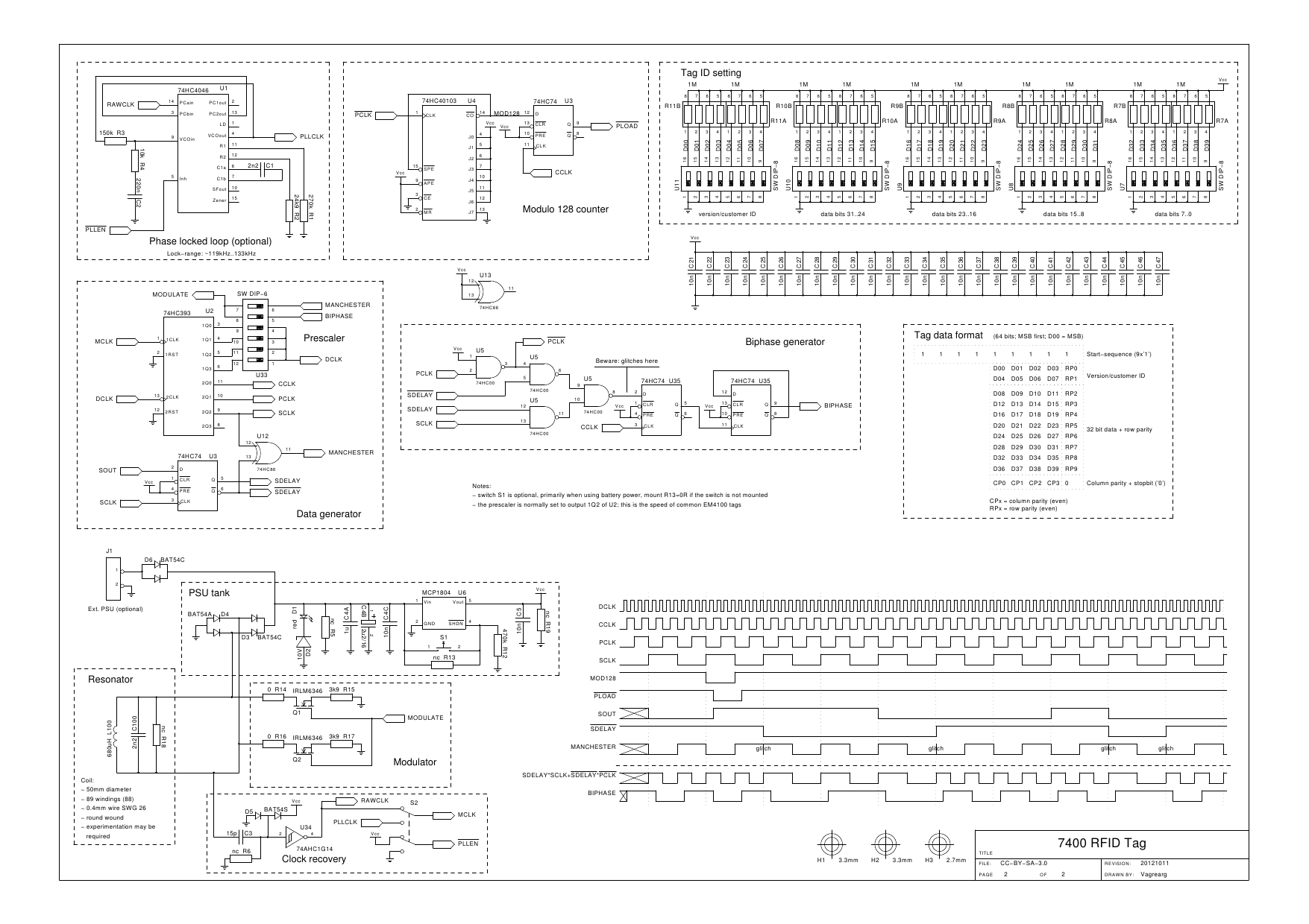
Multifunction Passive 7400 RFID Tag
Significant overengineering was necessary to replicate a previous capacitive scanner. At the local hackerspace OSAA, a brainstorming session was initiated with Pedersen, AsbjG rn, and Flemming, who quickly generated numerous creative ideas. The discussion took an interesting turn when Flemming,...
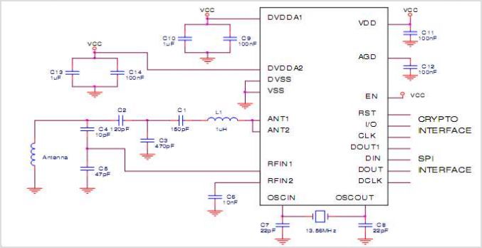
EM4294 13.56MHz Crypto Analogue Front End Circuit For High Secure RFID Communication
The EUA2032 is a high-efficiency, 2.5W mono class-D audio power amplifier. A newly developed filterless PWM modulation architecture further reduces EMI and THD+N, as well as eliminates the LC output filter, thereby reducing the external component count, system cost, and...