


wifi radio with lcd display
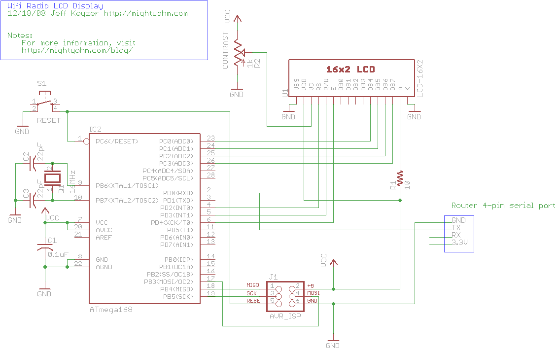
Description: This is the seventh part of an ongoing series about building a low-cost, open-source streaming internet radio. If you have not already, check out the previous parts for some background about the project. In part six, UNIX-style shell commands were used to interface with mpd, the music player daemon, and redirect song and stream information to the ASUS WL-520gU wireless router's serial port. In this part, a Sparkfun 16G-2 LCD display and several other components will be utilized to create an LCD status display for the radio. An Atmel ATmega168 AVR microcontroller has been chosen to drive the display, raising the technical complexity of the project. However, an Arduino, which uses the same ATmega168 microcontroller, could also be used effectively, and porting the program to an Arduino sketch should not be overly difficult. For those new to the AVR, numerous online tutorials are available to facilitate learning this affordable and powerful microcontroller. It is recommended to start with basic tutorials and to successfully run a simple blinking LED example on the AVR before proceeding with the LCD display project. Special acknowledgment is given to Peter Fleury for his excellent LCD library, which significantly simplifies the implementation. Assembling the circuit on a breadboard is straightforward. The router's serial port is wired to the breadboard, with the RX line currently unused. The USB AVR programmer also serves as a 5V power supply for the circuit, and it is essential to ensure the 2-pin jumper on the USBTinyISP is installed to enable the +5V supply. The LCD displays the current stream name, and experimentation with component placement on the breadboard is encouraged, provided the schematic is followed. The serial port connection to the router is made using a 4-pin female header, with wires soldered to the pins of the header. For those using AVR MacPack and OS X, the process should be straightforward, while PC users may need to adapt accordingly. The USBTinyISP should be connected to the computer and the breadboard, with the green light on the programmer indicating readiness and the LCD backlight showing that power is supplied.
The circuit design for the LCD status display involves several key components, including the Atmel ATmega168 microcontroller, the Sparkfun 16G-2 LCD display, and the USB AVR programmer. The ATmega168 microcontroller serves as the central processing unit, executing the code that controls the LCD and manages communication with the router. The LCD display is connected to the microcontroller via a series of data and control lines, allowing it to receive commands and display information dynamically.
Powering the circuit is critical; thus, the USB AVR programmer is utilized as a 5V power source, ensuring that all components operate within their specified voltage ranges. The schematic should include clear connections between the microcontroller, LCD display, and power supply, with appropriate bypass capacitors placed near the power pins of the microcontroller to filter noise and stabilize the voltage.
The serial port connection from the router to the microcontroller is also a vital aspect of this design. The RX line, although not currently utilized, should be considered for future expansion or functionality. The schematic should illustrate the pin configuration for the serial connection, ensuring that the communication protocol aligns with the requirements of the router and the microcontroller.
In terms of programming, the AVR microcontroller can be flashed using the provided Makefile, which compiles the C source files into executable code. The process involves compiling the main and LCD source files and linking them to create an executable file that can be burned onto the microcontroller. The use of libraries, such as Peter Fleury's LCD library, simplifies the code needed to interface with the LCD, allowing for efficient display management without extensive low-level programming.
Overall, this project not only enhances the functionality of the streaming internet radio but also serves as an educational platform for those interested in microcontroller programming and electronic circuit design.This is the seventh part of an ongoing series about building a low cost, open source streaming internet radio. If you haven`t already, check out the previous parts (see the links at the end of this article) for some background about the project.
In part six, we used OpenWrt`s UNIX-style shell commands to interface with mpd, the music player daemo n, and redirect song and stream information to our ASUS WL-520gU wireless router`s serial port. In this part, we`ll use a Sparkfun 16G—2 LCD display and a handful of other components to build an LCD status display for the radio. After much thought, I decided to use an Atmel ATmega168 AVR microcontroller to drive the display. I realize that this raises the technical level of this project significantly, but I have been wanting to feature an AVR project on the site and this is a great opportunity.
The truth is that an Arduino would work just as well and it shouldn`t be too difficult to port this program to an Arduino sketch. (The Arduino is built with the same ATmega168 microcontroller, after all. ) If anyone does this, let me know and I`ll post a link to your version of the display. If you are new to the AVR, don`t be intimidated. There are a number of tutorials online to help you learn how to use this inexpensive and powerful microcontroller.
I recommend starting with this one or maybe this one, but see my note about AVR MacPack below if you`re using a Mac. If you`ve never programmed in C before, you`ll have an additional hurdle to get over, although for this project you won`t need any actual knowledge of programming or C to burn the code to the AVR and get things working.
I recommend following a tutorial or two and getting a simple blinking LED example working on your AVR before building the LCD display. That way you can be sure your programmer, development environment, breadboard, etc are working first.
Special thanks to Peter Fleury for his excellent LCD library, which saved me from reinventing the wheel! He also has another page about interfacing LCD displays to an AVR. Assembling the circuit on the breadboard is pretty straightforward. Here`s a photo showing all components of the setup. The router is shown above with the serial port wired to the breadboard (the RX line is floating as we`re not using it yet).
The USB AVR programmer is on the right, where it is also functioning as a 5V power supply for the circuit. Make sure the 2-pin jumper on the USBTinyISP is installed, this enables the +5V supply. The LCD is shown displaying the current stream name ( DI. fm ). Here is a closeup of the components installed on the breadboard to show how I did things, feel free to experiment with the placement of components.
As long as you follow the schematic the circuit should still work. Here is a closeup of the serial port connection to the router, including the 4-pin female 0. 1 ³ header. I soldered wires to the pins of the female header (not the pins on the board). If you`re using AVR MacPack and OS X, this should be easy (since that`s what I`m using). PC guys will need to figure this out for themselves but hopefully the process is similar (please let me know if the Makefile works). Connect the USBTinyISP to your computer with the USB cable and to the breadboard with the ISP cable. The green light on the programmer should be on, indicating it is ready, and the backlight of the LCD should be lit, indicating that the breadboard is getting power.
macbook:temp jkeyzer$ unzip. /AVR_wifiradio_display. zip Archive:. /AVR_wifiradio_display. zip inflating: lcd. c inflating: lcd. h inflating: main. c inflating: main. hex inflating: Makefile macbook:temp jkeyzer$ make flash avr-gcc -Wall -Os -DF_CPU=16000000 -mmcu=atmega168 -c main. c -o main. o avr-gcc -Wall -Os -DF_CPU=16000000 -mmcu=atmega168 -c lcd. c -o lcd. o avr-gcc -Wall -Os -DF_CPU=16000000 -mmcu=atmega168 -o main. elf main. o lcd. o rm -f main. hex avr-objcopy -j. text -j. data -O
The circuit design for the LCD status display involves several key components, including the Atmel ATmega168 microcontroller, the Sparkfun 16G-2 LCD display, and the USB AVR programmer. The ATmega168 microcontroller serves as the central processing unit, executing the code that controls the LCD and manages communication with the router. The LCD display is connected to the microcontroller via a series of data and control lines, allowing it to receive commands and display information dynamically.
Powering the circuit is critical; thus, the USB AVR programmer is utilized as a 5V power source, ensuring that all components operate within their specified voltage ranges. The schematic should include clear connections between the microcontroller, LCD display, and power supply, with appropriate bypass capacitors placed near the power pins of the microcontroller to filter noise and stabilize the voltage.
The serial port connection from the router to the microcontroller is also a vital aspect of this design. The RX line, although not currently utilized, should be considered for future expansion or functionality. The schematic should illustrate the pin configuration for the serial connection, ensuring that the communication protocol aligns with the requirements of the router and the microcontroller.
In terms of programming, the AVR microcontroller can be flashed using the provided Makefile, which compiles the C source files into executable code. The process involves compiling the main and LCD source files and linking them to create an executable file that can be burned onto the microcontroller. The use of libraries, such as Peter Fleury's LCD library, simplifies the code needed to interface with the LCD, allowing for efficient display management without extensive low-level programming.
Overall, this project not only enhances the functionality of the streaming internet radio but also serves as an educational platform for those interested in microcontroller programming and electronic circuit design.This is the seventh part of an ongoing series about building a low cost, open source streaming internet radio. If you haven`t already, check out the previous parts (see the links at the end of this article) for some background about the project.
In part six, we used OpenWrt`s UNIX-style shell commands to interface with mpd, the music player daemo n, and redirect song and stream information to our ASUS WL-520gU wireless router`s serial port. In this part, we`ll use a Sparkfun 16G—2 LCD display and a handful of other components to build an LCD status display for the radio. After much thought, I decided to use an Atmel ATmega168 AVR microcontroller to drive the display. I realize that this raises the technical level of this project significantly, but I have been wanting to feature an AVR project on the site and this is a great opportunity.
The truth is that an Arduino would work just as well and it shouldn`t be too difficult to port this program to an Arduino sketch. (The Arduino is built with the same ATmega168 microcontroller, after all. ) If anyone does this, let me know and I`ll post a link to your version of the display. If you are new to the AVR, don`t be intimidated. There are a number of tutorials online to help you learn how to use this inexpensive and powerful microcontroller.
I recommend starting with this one or maybe this one, but see my note about AVR MacPack below if you`re using a Mac. If you`ve never programmed in C before, you`ll have an additional hurdle to get over, although for this project you won`t need any actual knowledge of programming or C to burn the code to the AVR and get things working.
I recommend following a tutorial or two and getting a simple blinking LED example working on your AVR before building the LCD display. That way you can be sure your programmer, development environment, breadboard, etc are working first.
Special thanks to Peter Fleury for his excellent LCD library, which saved me from reinventing the wheel! He also has another page about interfacing LCD displays to an AVR. Assembling the circuit on the breadboard is pretty straightforward. Here`s a photo showing all components of the setup. The router is shown above with the serial port wired to the breadboard (the RX line is floating as we`re not using it yet).
The USB AVR programmer is on the right, where it is also functioning as a 5V power supply for the circuit. Make sure the 2-pin jumper on the USBTinyISP is installed, this enables the +5V supply. The LCD is shown displaying the current stream name ( DI. fm ). Here is a closeup of the components installed on the breadboard to show how I did things, feel free to experiment with the placement of components.
As long as you follow the schematic the circuit should still work. Here is a closeup of the serial port connection to the router, including the 4-pin female 0. 1 ³ header. I soldered wires to the pins of the female header (not the pins on the board). If you`re using AVR MacPack and OS X, this should be easy (since that`s what I`m using). PC guys will need to figure this out for themselves but hopefully the process is similar (please let me know if the Makefile works). Connect the USBTinyISP to your computer with the USB cable and to the breadboard with the ISP cable. The green light on the programmer should be on, indicating it is ready, and the backlight of the LCD should be lit, indicating that the breadboard is getting power.
macbook:temp jkeyzer$ unzip. /AVR_wifiradio_display. zip Archive:. /AVR_wifiradio_display. zip inflating: lcd. c inflating: lcd. h inflating: main. c inflating: main. hex inflating: Makefile macbook:temp jkeyzer$ make flash avr-gcc -Wall -Os -DF_CPU=16000000 -mmcu=atmega168 -c main. c -o main. o avr-gcc -Wall -Os -DF_CPU=16000000 -mmcu=atmega168 -c lcd. c -o lcd. o avr-gcc -Wall -Os -DF_CPU=16000000 -mmcu=atmega168 -o main. elf main. o lcd. o rm -f main. hex avr-objcopy -j. text -j. data -O
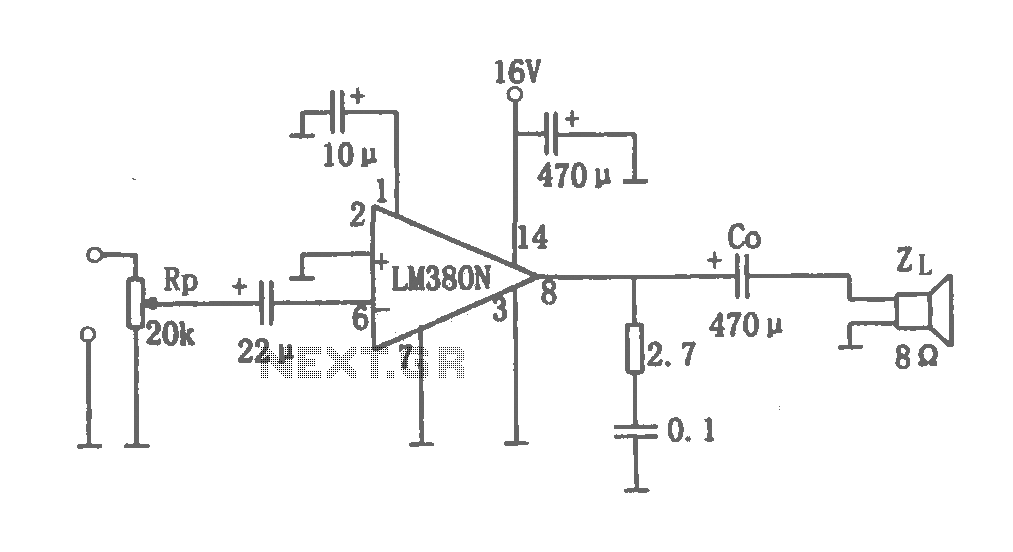
2W audio power amplifier LM380 circuit
This document details a 2W audio power amplifier circuit that utilizes a 14-pin LM380 package as the amplification element. The input signal is managed by a volume control potentiometer (Rp) rated at 20k ohms, with a coupling capacitance of 22...
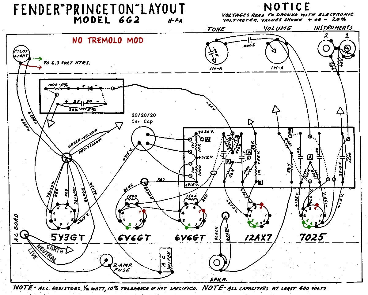
6G2 amp volume and tone play up on one input only
A newcomer is seeking a welcoming environment and expresses a desire to share a considerable amount of information.
In the context of electronic schematics, it is essential to facilitate an inclusive environment for individuals at all levels of expertise. This can...

22W Stereo Amplifier Using TDA1554
This document presents a 22-watt stereo audio power amplifier circuit diagram based on the TDA1554 integrated circuit from NXP Semiconductors (formerly Philips Semiconductors).
The 22-watt stereo audio power amplifier circuit utilizing the TDA1554 IC is designed to deliver high-quality audio amplification...
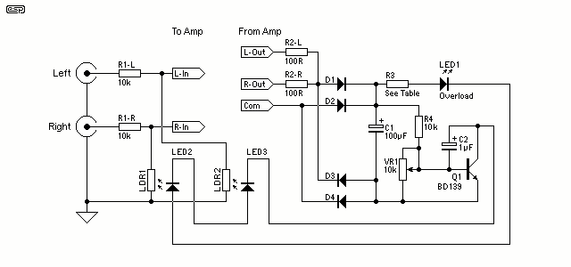
Audio Power Limiter
The gain control element is a Light Dependent Resistor (LDR). These are blessed with a few very useful features for our purposes, one of which is low distortion even at quite high signal levels. Being light activated, all we need...
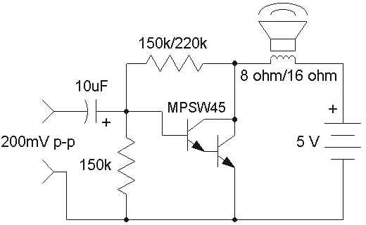
Audio Amplifiers
The first choice is usually an integrated circuit designed for the purpose. A typical assortment can be seen on this National Semiconductor page. Discrete designs can also be built with readily available transistors or op-amps, and many designs are featured...
NAD C 520
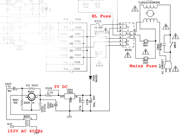
The LCD display on the NAD C520 compact disc player has become unreadable. The audio and CD deck are functioning properly, but operating the unit without a legible display is challenging. When viewed under the right lighting, the basic LCD...
Audio High Gain Crystal Earphone Amplifier
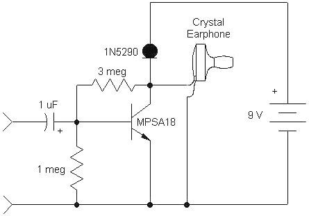
This simple, one-transistor amplifier provides a voltage gain of over 1000 (60 dB) for an active aerial impedance crystal earphone. The gain is achieved by replacing the standard load resistor with a constant-current diode that supplies 1/2 mA while exhibiting...

Auto Loudness Control
Simple add-on module. A simple approach to this problem can be done inserting a circuit in the preamplifier stage, capable of varying automatically the frequency response of the entire audio chain in respect to the position of the control knob,...
FFT audio amplifier design
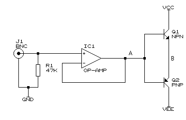
For all the subsequent tests, a high-quality signal generator from BlackStar was utilized. The PicoScope trace displayed below illustrates a pure 1 kHz tone from the signal generator. It is important to note that while the screenshots below depict the...