


wireless microphone circuit
#FM
#microphone
#frequency modulation
#radio frequency
#transmitter
#audio
#variable circuit
#broadcast
#reception
#sound
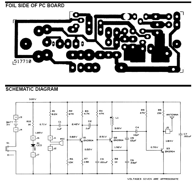
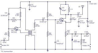
Description: The frequency range for the FM transmission band is 90 MHz (megahertz, or 90 million cycles per second). Due to the variable tuned circuit in the FM transmitter, it can be tuned to a specific frequency within the local FM broadcast band for optimal reception. When sound waves strike the small microphone, they are converted into a change in current through resistor R1 (refer to the schematic diagram). This electrical change is amplified and subsequently frequency modulates the transmitter. The operational range of the FM microphone is approximately 100 feet, depending on the effectiveness of the antenna (whether it is properly tuned or not) and the quality of the FM radio receiver.
The FM transmitter circuit operates within the specified frequency range of 90 MHz, which is crucial for compatibility with standard FM radio receivers. The inclusion of a variable tuned circuit allows for precise frequency adjustment, enabling the transmitter to be aligned to a specific frequency that minimizes interference and maximizes clarity.
The small microphone serves as the transducer, converting acoustic energy from sound waves into electrical energy. This conversion occurs through a diaphragm that vibrates in response to sound, generating a corresponding change in current. Resistor R1 plays a critical role in this process by providing a load for the microphone and helping to shape the signal for amplification.
The amplified signal is then fed into a modulator circuit, which applies frequency modulation to the carrier wave generated by an oscillator. This modulation process encodes the audio information onto the carrier wave, allowing it to be transmitted over the airwaves.
The operational range of the FM microphone, approximately 100 feet, is influenced by several factors. The design and tuning of the antenna significantly affect the transmission range, as a well-tuned antenna can efficiently radiate the modulated signal. Additionally, the sensitivity and selectivity of the receiving FM radio also play a vital role in determining the effective range and quality of the received signal.
In summary, this FM transmitter circuit is designed for effective audio transmission over short distances, utilizing a combination of microphone conversion, amplification, and frequency modulation to deliver clear sound to standard FM receivers. Proper tuning and antenna design are essential for optimal performance.The ambit of frequencies for the FM advertisement bandage is 90MHz (MHz = Megahertz or 90 actor cycles per second). Because the FM microphone has a capricious acquainted circuit, it can be acquainted to a quiet atom on your bounded FM advertisement bandage for the best reception.
When the baby microphone aspect is addled by sound, it converts the audio to a change in accepted through resistor R1 (see schematic diagram). This electrical change is amplified and eventually abundance modulates the transmitter. The manual ambit of the FM microphone is about 100 feet, depending on the ability of the antenna (properly acquainted or not) and the affection of the FM radio receiver.
The FM transmitter circuit operates within the specified frequency range of 90 MHz, which is crucial for compatibility with standard FM radio receivers. The inclusion of a variable tuned circuit allows for precise frequency adjustment, enabling the transmitter to be aligned to a specific frequency that minimizes interference and maximizes clarity.
The small microphone serves as the transducer, converting acoustic energy from sound waves into electrical energy. This conversion occurs through a diaphragm that vibrates in response to sound, generating a corresponding change in current. Resistor R1 plays a critical role in this process by providing a load for the microphone and helping to shape the signal for amplification.
The amplified signal is then fed into a modulator circuit, which applies frequency modulation to the carrier wave generated by an oscillator. This modulation process encodes the audio information onto the carrier wave, allowing it to be transmitted over the airwaves.
The operational range of the FM microphone, approximately 100 feet, is influenced by several factors. The design and tuning of the antenna significantly affect the transmission range, as a well-tuned antenna can efficiently radiate the modulated signal. Additionally, the sensitivity and selectivity of the receiving FM radio also play a vital role in determining the effective range and quality of the received signal.
In summary, this FM transmitter circuit is designed for effective audio transmission over short distances, utilizing a combination of microphone conversion, amplification, and frequency modulation to deliver clear sound to standard FM receivers. Proper tuning and antenna design are essential for optimal performance.The ambit of frequencies for the FM advertisement bandage is 90MHz (MHz = Megahertz or 90 actor cycles per second). Because the FM microphone has a capricious acquainted circuit, it can be acquainted to a quiet atom on your bounded FM advertisement bandage for the best reception.
When the baby microphone aspect is addled by sound, it converts the audio to a change in accepted through resistor R1 (see schematic diagram). This electrical change is amplified and eventually abundance modulates the transmitter. The manual ambit of the FM microphone is about 100 feet, depending on the ability of the antenna (properly acquainted or not) and the affection of the FM radio receiver.
tda2004-stereo-bridge-audio-amplifier.html
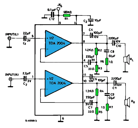
The TDA2004 integrated circuit (IC) is a popular choice among audio electronics enthusiasts due to its affordability and availability. This IC is often utilized in audio amplifier designs because it features two outputs and inputs, making it easy to implement...
Audio-To-Adc Interface Circuit
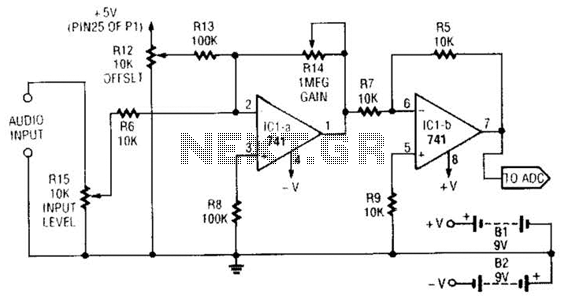
This simple general-purpose driver for an analog/digital converter uses two 741 IC devices with adjustable gain and offset. Other op-amps might be substituted, but some circuit adjustments might be needed.
The circuit consists of two operational amplifiers (op-amps) from the 741...
The input circuit common mode noise suppression microphone amplifier with balance
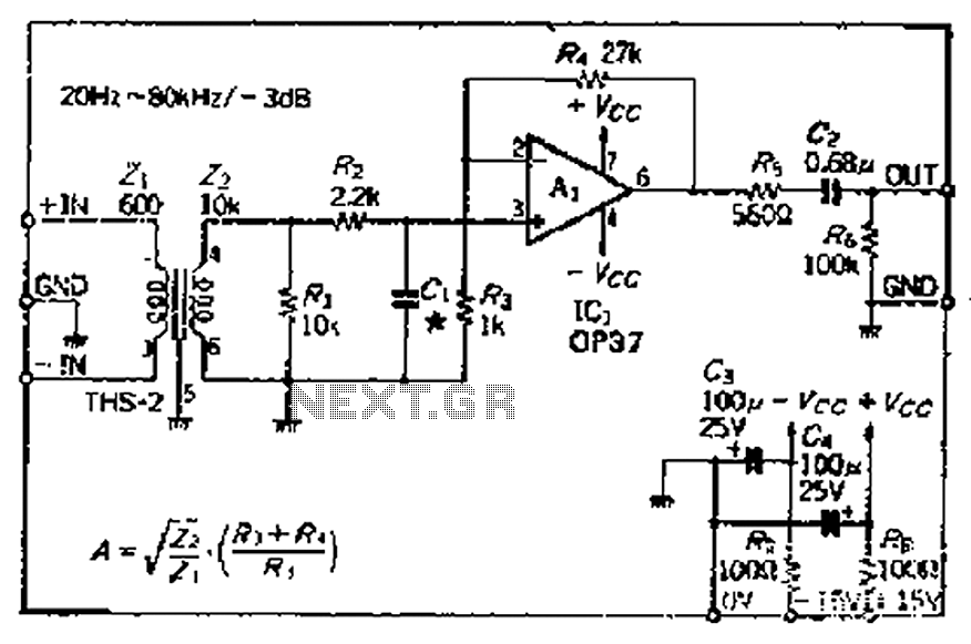
The common mode signal rejection ratio is influenced by the input transformer, which should either be a commercially available or a well-balanced homemade transformer. It is important to note that as frequency increases, the balance may decrease. The transmission frequency...
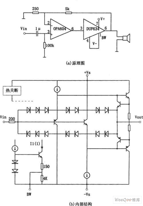
OPA604 High Performance and Small Power Audio Amplifier
The provided image depicts a high-performance and low-power audio power amplifier circuit. The initial stage utilizes the MOSFET hi-fi operational amplifier OPA604, while the subsequent stage employs the high-speed buffer BUF634. Voltage series negative feedback is implemented between the two...
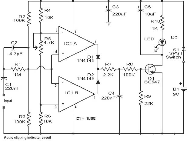
Audio Clipping Detector Circuit
Clipping is a significant issue that leads to distortion in amplifiers. It results in the amplitude level of a waveform dropping abruptly before it reaches its intended limit. This document presents a straightforward circuit designed to detect clipping in a...
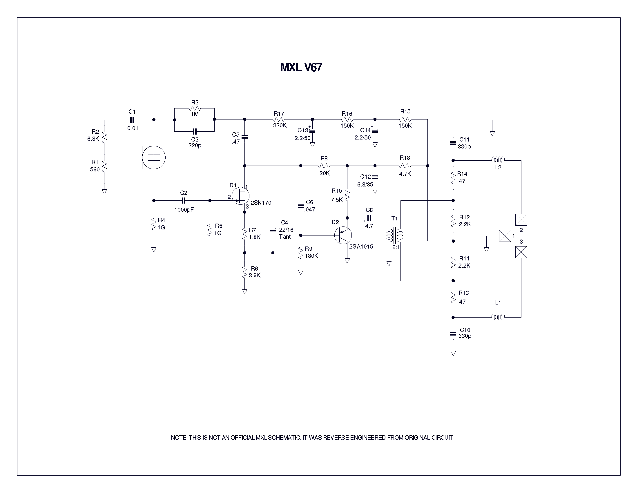
understanding a mic circuit
A user has been experimenting with modifications to a budget-friendly MXL V67s microphone to enhance its performance, specifically aiming to improve the condenser quality until a higher-end model can be acquired.
The MXL V67s is a popular choice among budget-conscious audio...
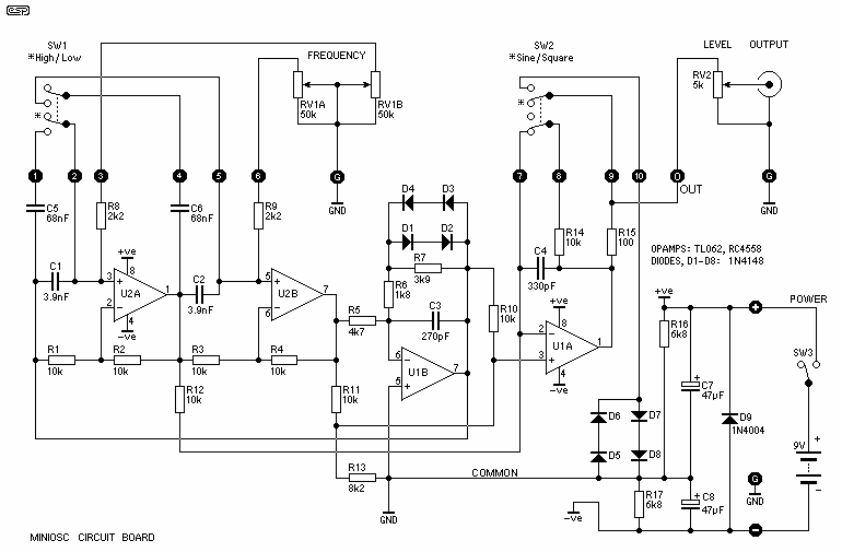
Audio Oscillator schematic
The oscillator circuit involves two unity gain phase shift stages, A1 and A2, in tandem and a gain stage, A3, with back to back diodes and resistor network providing non-linear negative feedback. At a particular frequency (determined by RT and...

Using the Panasonic WM61A as a Measurement Microphone
Measurement microphones differ from recording microphones and sound meters; they have a flat response (usually well below 20 Hz and above 20 kHz) and do not have a "weighted" or equalized frequency response. They are optimized for measuring high SPL...
televition transmitter
The camera is oriented to look out the side of the rocket during launch and downward during descent on the parachute. An optional external mirror can be added to enable the camera to look down during lift-off. The transmitter antenna,...