
Clap-Sensitive Relay with ON/OFF Feature
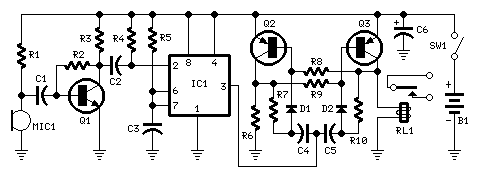
Circuit Explanation: The circuit operates by activating a single-pole double-throw (SPDT) reed relay with a hand clap, while a subsequent clap deactivates the relay. To prevent erratic operation, the circuit's sensitivity has been intentionally reduced, ensuring that a loud clap will reliably toggle the relay when detected by the electret microphone. The TS555 timer, functioning in monostable mode, generates a clean output signal with a defined time delay, facilitating proper switching of the bistable circuit. The monostable mode generates a single pulse upon receiving a trigger signal, while the bistable mode operates similarly to a flip-flop or Schmitt trigger, producing set and reset states.
The transistor Q1 acts as an audio amplifier, while Q2, in conjunction with Q3 and other components, forms a discrete circuit that drives the relay, allowing operation from a 3 V supply. When energized, the relay increases the circuit's current drain to 20 mA; however, during standby or idle conditions, the circuit consumes less than 1 mA. Despite the supply voltage being only 3 V, derived from two 1.5 V AA or AAA cells in series, a small DIL 5 V reed relay is utilized. Testing has shown that these relays can operate with coil voltages in the range of 1.9 V to 2.1 V, with coil resistances varying from 140 Ohms to 250 Ohms. This clap relay circuit can be employed in various applications, particularly beneficial for elderly or disabled individuals, allowing them to control lighting and other appliances with a simple hand clap, as long as the microphone is capable of detecting the sound.Terminology TS555 a single CMOS timer which offers very low power consumption and high frequency where the timing remains very accurate in monostable or astable mode while providing reduced supply current spikes during output transitions, which enables the use of lower decoupling capacitors and with added features of high output current capabil ity, high input impedance, wide voltage range, and output compatible with TTL, CMOS & Logic MOSBC550 an NPN general purpose transistor with low current and low voltage used for low noise stages in audio frequency equipmentBC328 a PNP general purpose transistor in a TO-92 package, used for general purpose switching and amplifier applications which is suitable for AF driver stages and low power output stages of audio amplifiers due to its features of high current at 500 mA maximum and low voltage at 45 V maximumCircuit Explanation During the operation of the circuit, a hand clap would activate a SPDT reed relay while a further clap will turn OFF the relay. In order to prevent unpredictable operation, the sensitivity of the circuit was reduced on purpose. This reduction of sensitivity will make sure that a loud hand clap will switch the relay to ON/OFF without failure when received from the electret microphone.
A clean output signal is being provided by the IC1 timer as it operates in a monostable mode along with a reasonable time delay so that the proper switching of the bistable circuit will be allowed. The monostable mode produces a single pulse upon receiving a trigger signal while a bistable mode produces a state of set and reset as with a flip flop or Schmitt trigger.
An audio amplifier is being acted by Q1 while Q2 forms a discrete-components circuit together with Q3 and other related parts for this purpose. This formation directly drives the relay and allows the operation of a 3 V supply. The current drain of the circuit is increased to 20 mA when the relay has been energized. However, the current consumption of the circuit will be less than 1 mA during standby or idle state. Even if the voltage supply is only 3 V, coming from two 1. 5 V AA or AAA cells in series, a small DIL 5 V reed relay was still used for the circuit. This is because of the tests done on several devices of this type where it was found out that they can be powered ON with a coil voltage value in the range of 1.
9 V to 2. 1 V. The values of the coil resistance are varying from 140 Ohms to 250 Ohms. The clap relay circuit may be utilized in several beneficial applications especially for elderly or disabled people where the lighting can be operated with a simple hand clap. It can also be used with other types of appliances for as long as the microphone would be capable of hearing the hand claps.
🔗 External reference
Related Circuits
A relay is an isolated switch, with no direct connection between the switching device and the load. Relays are commonly used to control high-voltage devices, protecting sensitive low-voltage components from damage. Various types of relays exist, but electromechanical relays...

This circuit design for a low current relay is intended for use in battery-operated electronic devices, with an operating current in microamperes (µA). It utilizes a bistable relay and additional components to enable the relay to function similarly to...
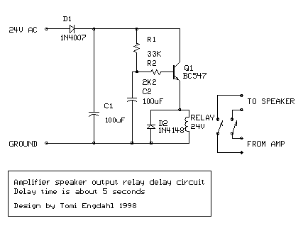
This is a simple circuit designed for an audio amplifier project to control the speaker output relay. The purpose of this circuit is to manage the delay that activates the relay, which connects the speakers to the audio amplifier....

This design uses a smart card to enable a relay. A Nutchip recognizes its mating smart card among thousand similar ones, because you choose the code to be programmed in the card's memory. No specialized knowledge is necessary, as...
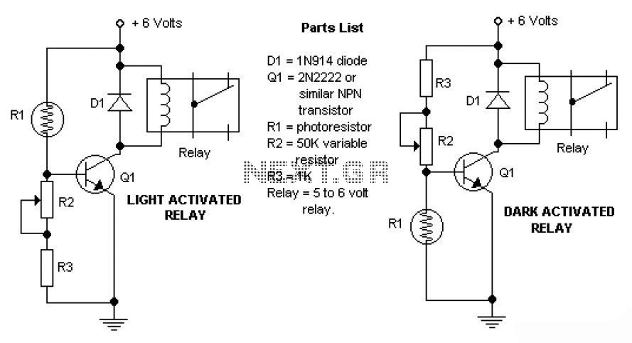
This is a basic dark and light sensor that uses a photoresistor as the sensing component. The transistor functions as a switch; when the switch is in the "on" condition, the relay will be activated. The potentiometer adjusts the...
While many power supplies can be set to limit their output current to a defined level to protect the circuit they are powering, no such protection is available. To enhance the safety and reliability of electronic circuits, it is crucial...
Warning: include(partials/cookie-banner.php): Failed to open stream: Permission denied in /var/www/html/nextgr/view-circuit.php on line 713
Warning: include(): Failed opening 'partials/cookie-banner.php' for inclusion (include_path='.:/usr/share/php') in /var/www/html/nextgr/view-circuit.php on line 713