
Class E AM Transmitter for 1710 kHz
The 200-watt class-E AM transmitter operates at a frequency of 1710 kHz, which is in the medium wave AM broadcast band. Class-E amplifiers are known for their high efficiency, typically exceeding 80%, which makes them suitable for applications requiring significant power output with minimal heat generation. In this design, the transmitter utilizes a negative peak limiter to prevent distortion during high modulation peaks, ensuring audio quality remains intact while transmitting.
The over-modulation indicator serves as a critical feature, alerting the operator when the modulation level exceeds acceptable limits. This is essential for maintaining compliance with broadcasting standards and preventing interference with adjacent channels. The linear scale directional wattmeter included in the schematic allows for accurate measurement of the transmitter's output power, facilitating adjustments to ensure optimal performance.
Power supply circuits are integral to the operation of the transmitter, providing the necessary voltage and current to the amplifier stages. The design may incorporate voltage regulation and filtering components to ensure stable operation under varying load conditions. Additionally, the antenna circuits facilitate efficient radiation of the transmitted signal, which is crucial for effective broadcasting.
Overall, this transmitter design combines advanced features to achieve reliable and high-quality AM broadcasting, while also addressing the need for monitoring and compliance with broadcasting regulations.A 200-watt class-E AM transmitter used for non-sanctioned broadcasting on 1710 kHz. Negative peak limiter, over-modulation indicator, linear scale directional wattmeter, power supply and antenna circuits (schematic diagram) are also shown.. 🔗 External reference
Related Circuits

Building a signal generator is an essential project for any analog DIY enthusiast. While already possessing a bench signal generator, the intention was to create a compact, battery-powered device for quickly testing new effect designs. An enclosure from a...

The DPT Transmitter is a dual-powered voice transmitter designed to operate in two modes: a high-power mode for long-range transmission and a low-power mode for extended battery life. It functions at a low power level of 100 mW and...
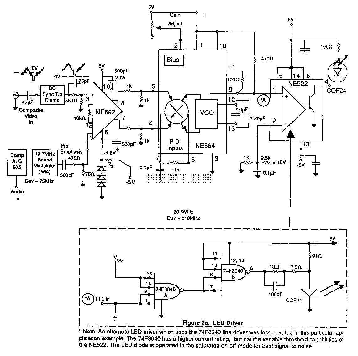
An alternate LED driver utilizing the 74F3040 line driver has been implemented in this application example. The 74F3040 offers a higher current rating but lacks the variable threshold capabilities found in the NE522. The LED diode operates in a...
The input stage is comprised of both halves of a 6SL7 octal dual hi-mu triode in a differential amp configuration with a 1mA constant current cathode load. Field-effect (constant-current) diodes are used for simplicity. The differential amp approach was...
Integrated circuits (ICs) that were once prohibitively expensive for hobbyists are now more affordably priced. A notable example is the AD8099 from Analog Devices, which is available for a modest cost. The AD8099 is a high-speed operational amplifier (op-amp)...
The frequency range is 100-108 MHz. The circuit is a mono circuit that accepts audio input from either a microphone or another source. The input impedance is 1 MΩ, with an input sensitivity of 5 mV and a maximum...
Warning: include(partials/cookie-banner.php): Failed to open stream: Permission denied in /var/www/html/nextgr/view-circuit.php on line 713
Warning: include(): Failed opening 'partials/cookie-banner.php' for inclusion (include_path='.:/usr/share/php') in /var/www/html/nextgr/view-circuit.php on line 713