
Closed-loop-motor-speed-control
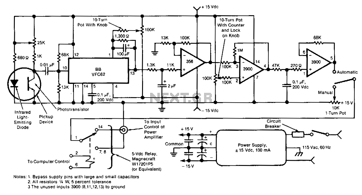
This electronic motor-speed control circuit is designed to operate in an electrically noisy environment. The circuit includes an optoelectronic pickup device, which is placed inside the motor housing to provide a speed feedback signal. The circuit automatically maintains the speed of the motor at the commanded value. The pickup device contains an infrared LED and a phototransistor. The radiation from the diode is chopped into pulses by the motor fan blades, which are detected by the phototransistor. The train of pulses from the phototransistor is fed to a frequency-to-voltage converter, the output of which is a voltage proportional to the speed of the motor. This voltage is low-pass filtered, amplified, and compared with a manually adjustable control voltage that represents the commanded speed. The difference between the speed measurement and speed command signals is amplified and fed as a control voltage to an external power amplifier that drives the motor. A selector switch at the output of the final amplifier of this circuit also enables the operator to bypass the circuit and manually set the control voltage for the external amplifier.
The motor-speed control circuit is engineered to function effectively in environments with significant electrical interference, ensuring reliable operation under challenging conditions. At its core, the system utilizes an optoelectronic pickup device, strategically positioned within the motor housing. This device comprises an infrared LED and a phototransistor, which work in tandem to generate a feedback signal related to the motor's rotational speed. As the motor operates, the LED emits infrared light that is intermittently obstructed by the motor's fan blades, resulting in a series of pulses detected by the phototransistor.
These pulses are then processed through a frequency-to-voltage converter, which translates the frequency of the incoming pulse train into a corresponding voltage level that reflects the motor's speed. This voltage output undergoes low-pass filtering to smooth out any rapid fluctuations, followed by amplification to ensure it is at an adequate level for comparison. The amplified voltage is then compared to a manually adjustable control voltage, which represents the desired speed set by the operator.
The circuit's control mechanism relies on the difference between the actual speed (as measured by the feedback system) and the commanded speed. This difference is amplified and transformed into a control voltage that drives an external power amplifier, which, in turn, regulates the power supplied to the motor. Additionally, a selector switch is incorporated at the output stage of the final amplifier, providing the operator with the option to bypass the automated control system. This feature allows for manual adjustment of the control voltage directly, offering flexibility in controlling the motor's speed according to specific operational needs. The overall design emphasizes robustness and adaptability, making it suitable for a variety of applications where precise motor speed regulation is critical.This electronic motor-speed control circuit is designed to operate in an electrically noisy environment. The circuit includes an optoelectronic pickup device. whichis placed inside the motor housing to provide a speed feedback signal. The circuit automatically maintains the speed of the motor at the commanded value. The pickup device contains an infrared LED and a phototransistor. The radiation from the diode is chopped into pulses by the motor fan blades. which are detected by the phototransistor. The train of pulses from the phototransistor is fed to a frequency-to-voltage converter, the output of which is a voltage proportional to the speed of the motor. This voltage is low-pass filtered, amplified, and compared with a manually-adjustable control voltage that represents the commanded speed.
The difference between the speed-measurement and speed-command signals is amplified and fed as a control voltage to an external power amplifier that drives the motor. A selector switch at the output of the final amplifier of this circuit also enables the operator to bypass the circuit and manually set the control voltage for the external amplifier.
🔗 External reference