
Closed-loop-tracer
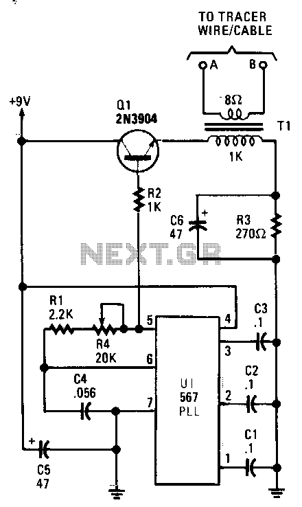
The tracer, which includes both a transmitter and receiver, is designed to trace a closed-loop wire or cable system. It follows the path of an induced voltage created by feeding a low-current, audio-frequency signal through the cable. When the pick-up coils come close to the current-carrying cable, a small voltage is generated in each coil, and this induced voltage is processed by the receiver's circuitry. The circuit is built around a 567 phase-locked loop (PLL) configured as a variable-frequency audio generator, producing a square-wave output at pin 5. Potentiometer R4 allows for easy tuning of the oscillator to the receiver's frequency. Transistor Q1 isolates the oscillator from the load and matches the impedance of the primary of transformer T1. Resistor R3 limits the current flow through Q1, while the low-impedance secondary of T1 supplies the cable drive signal.
The tracer circuit operates by utilizing a combination of a transmitter and a receiver to effectively follow a closed-loop wire or cable system. The core functionality relies on the generation of an induced voltage along the cable, achieved by introducing a low-current audio-frequency signal. This signal travels through the cable, and when the pick-up coils are positioned near the current-carrying cable, they detect the resulting induced voltage. The small voltage generated in the coils is subsequently processed by the receiver circuitry, allowing for accurate tracing of the cable's path.
At the heart of the circuit is a 567 phase-locked loop (PLL), which is configured to serve as a variable-frequency audio generator. This PLL is capable of producing a square-wave output at pin 5, which is crucial for the operation of the tracer. The tuning of the oscillator to match the receiver's frequency is facilitated by the inclusion of potentiometer R4, allowing for precise adjustments based on the specific requirements of the tracing task.
To ensure effective operation, transistor Q1 is employed to isolate the oscillator from the load, thereby preventing any potential interference that could arise from the load's characteristics. Furthermore, Q1 also plays a critical role in matching the impedance to the primary winding of transformer T1. This impedance matching is essential for optimizing signal transfer and maintaining the integrity of the audio signal.
Resistor R3 is incorporated into the circuit design to limit the current flowing through transistor Q1, thereby protecting the transistor from excessive current that could lead to damage. The secondary winding of transformer T1 is designed to be low-impedance, which is advantageous for supplying the necessary cable drive signal. This drive signal is what ultimately enables the tracing of the cable, as it interacts with the induced voltage within the closed-loop system.
Overall, the design of the tracer circuit combines various electronic components and principles to create an effective tool for tracing closed-loop wire or cable systems, making it a valuable asset in various applications, including telecommunications, electrical maintenance, and troubleshooting.The tracer, consisting of both a transmitter and receiver, is designed to follow a closed-loop wire or cable system. It follows an induced voltage path created by feeding a low-current, audio-frequency signal through the cable.
When the pick-up coils come within close proximity of the current -carrying cable, a small voltage is generated in each coil, and that induced voltage is then processed by the receiver"s circuitry. The circuit is built around a 567 phase-locked loop (PLL) configured as a variable-frequency, audio-generator circuit, which is designed to produe
Resistor R3 limits current flow through Ql. The low-impedance secondary of T1 supplies the cable drive signal. 🔗 External reference
Warning: include(partials/cookie-banner.php): Failed to open stream: Permission denied in /var/www/html/nextgr/view-circuit.php on line 713
Warning: include(): Failed opening 'partials/cookie-banner.php' for inclusion (include_path='.:/usr/share/php') in /var/www/html/nextgr/view-circuit.php on line 713