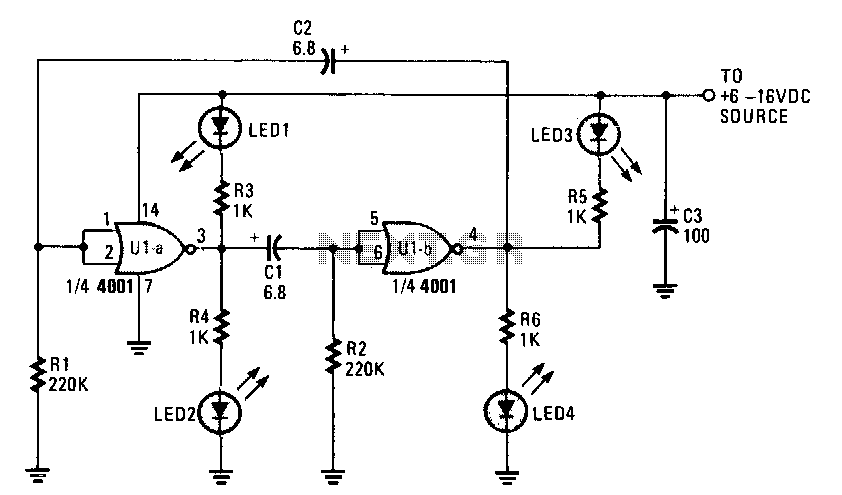
Cmos-flasher

This circuit utilizes a low-cost CMOS integrated circuit (IC) to control four light-emitting diodes (LEDs), turning them on and off at a frequency determined by the resistor values R1 and R2, as well as the capacitor values C1 and C2. With the specified values for R1 and R2, the pulse period is approximately four seconds. If R1 and R2 are reduced to 220 kΩ, the pulse rate increases to 1 Hz. The LEDs are activated in pairs: LED1 and LED4 illuminate simultaneously for half of the cycle, while LED2 and LED3 activate during the other half. The duration of illumination for each pair can be adjusted by modifying the capacitance of either C1 or C2. Increasing the value of either capacitor by a factor of ten will proportionally extend the ON time of the respective LED pair.
This circuit is designed around a CMOS IC, which is known for its low power consumption and high noise immunity, making it suitable for battery-operated devices. The configuration allows for a simple yet effective method of controlling the flashing of LEDs. The choice of resistors R1 and R2 directly influences the charging and discharging times of the capacitors C1 and C2, thereby setting the frequency of the LED flashes.
When R1 and R2 are set to higher values, the time constant of the RC circuit increases, resulting in a slower flash rate. Conversely, lowering these resistances increases the current flow, reducing the time constant and thus increasing the frequency of the LED flashing. The circuit can be further fine-tuned by adjusting the capacitors C1 and C2. These capacitors store charge and release it at a rate that can be controlled, allowing for precise timing of the LED activation.
The pairing of LEDs is an important feature of this design. By illuminating pairs of LEDs alternately, the circuit creates a visually appealing effect. The choice of which LEDs to pair can be modified based on the desired aesthetic or functional outcome. The circuit can be used in various applications, including decorative lighting, indicators, or as part of a larger electronic project where visual signaling is required.
In summary, this circuit provides a flexible platform for LED control, allowing for adjustments in both flash rate and duration through simple changes to the resistors and capacitors. This adaptability makes it a valuable tool for hobbyists and engineers alike who are looking to implement LED signaling in their designs.Uses a low cost CMOS IC to tum four LEDs on and off at a rate that is set by the values of R1, R2, Cl, and C2. The pulse rate for the component values given for R1 and R2 is about one cycle every four seconds. By lowering the values of Rl and R2 to 220 KO, the pulse rate increases to 1Hz. The LEDs flash in pairs, with LEDl and LED4 turning together for one half of the time period, while LED2 andLED3 are on for the other half.
The on/off duration of each pair of LEDs can be increased or decreased by changing the value of one of coupling capacitors C1 or C2. Increasing either capacitor"s value by a factor of 10 will also increase the ON time of a pair of the LEDs for about the same factor.
🔗 External reference