
Cmos-short-pulse-generator
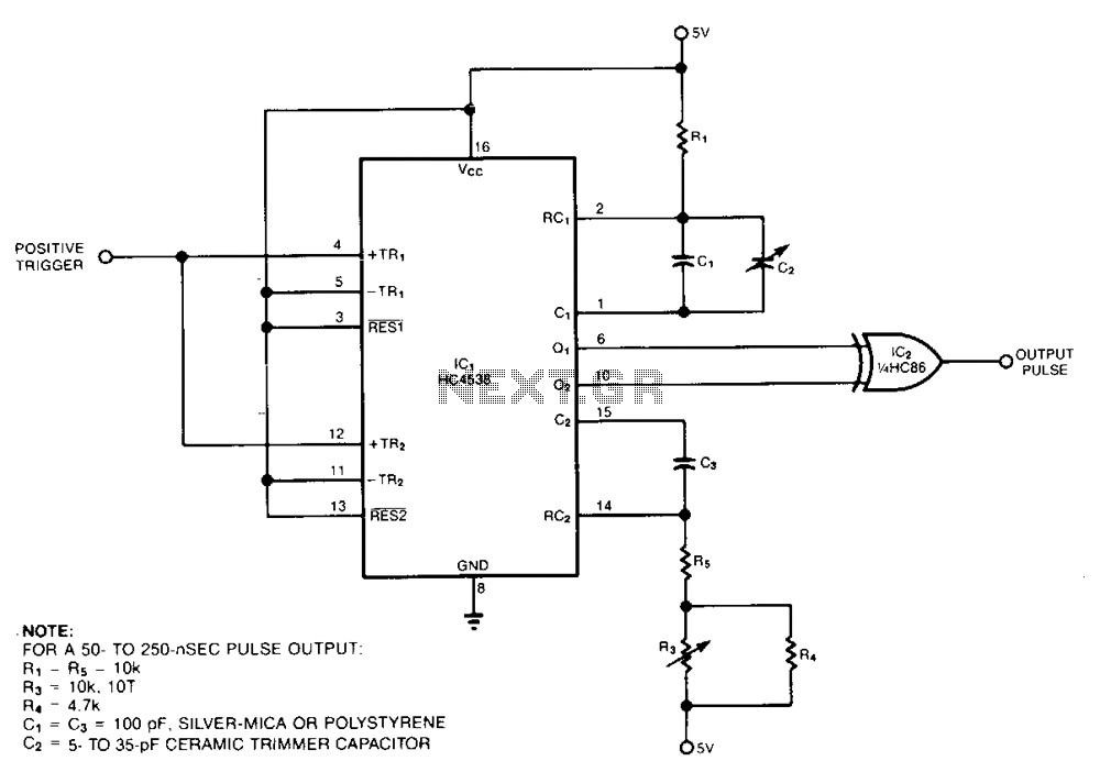
The pulse generator consists of two low-power CMOS chips that produce a precise pulse width ranging from 50 to 500 ns. IC1 is a dual monostable multivibrator (one shot) where each positive trigger pulse initiates simultaneous positive output pulses at pins 6 and 10. In response, the XOR gate IC2 generates a positive pulse whose duration is equal to the difference between the two input pulse durations. Section 1 of the one shot generates an approximate 1-µs reference pulse; shorter pulses are more susceptible to manufacturing variations caused by parasitic layout capacitance. A variable capacitor C2 allows for adjustment of this pulse width. Section 2 of the one shot generates a variable-length pulse, with its width adjustable via potentiometer R3. Resistors R4 and R5 define the maximum and minimum output pulse widths, respectively. Given that the XOR gate's rise and fall times are approximately 20 ns for reasonable load capacitance values, calibration of the circuit using C2 should be performed to achieve a minimum output width of 50 ns.
The pulse generator circuit is designed for applications requiring precise timing and pulse width modulation. The use of low-power CMOS technology ensures minimal energy consumption while maintaining high-speed performance. The dual monostable multivibrator, IC1, is critical for generating defined pulse outputs in response to input triggers. Each output pulse at pins 6 and 10 is synchronized, providing a coherent timing signal that can be utilized in various digital applications.
The XOR gate, IC2, plays a pivotal role in determining the duration of the output pulse. By comparing the input pulse durations, it effectively generates a pulse whose length is dictated by the difference in timing of the two inputs. This feature is particularly useful in applications that require pulse width adjustment based on varying input signals.
The design includes a variable capacitor, C2, which provides the ability to fine-tune the pulse width. This adjustability is essential for applications where precise timing is critical. The second section of the monostable multivibrator allows further customization of the output pulse length through potentiometer R3, enabling users to set the desired pulse width dynamically.
Resistors R4 and R5 are strategically included to set the bounds for the output pulse widths. R4 establishes the maximum pulse width, while R5 limits the minimum pulse width. The calibration process is necessary to ensure that the output pulse meets the specified minimum width of 50 ns, which is essential for maintaining signal integrity and reliability in high-speed digital circuits.
Overall, this pulse generator circuit is a versatile tool for engineers and designers in fields such as telecommunications, signal processing, and embedded systems, where accurate timing and pulse generation are paramount.Comprising two low-power, CMOS chips, thepulse generator produces a precise pulse width in the 50 to 500 ns range. ICl is a dual monostable multivibrator (one shot) in which each positive trigger pulse initiates simultaneous positive output pulses at pins 6 and 10.
In response, XOR gate IC2 produces a positive pulse whose duration is equal to the difference between the two input-pulse durations. Section 1 of the one shot generates an approximate 1-~ts reference pulse-shorter pulses are more susceptible to manufacturing variations caused by parasitic layout capacitance.
Variable capacitor C2 lets you adjust this pulse width. Section 2 of the one shot generates a variable-length pulse; you adjust its width by using potentiometer R3. Resistors R4 and R5 set the output pulse"s maximum and minimum width, respectively. Because the XOR gate"s rise and fall times are about 20 ns for reasonable values of load capacitance, you should calibrate the circuit using C2 for a minimum output-width of 50 ns.
🔗 External reference