
Code-practice-oscillator
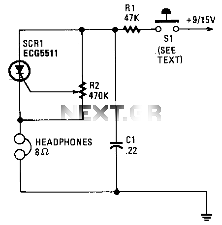
Capacitor C1 charges through resistor R1, and when the gate level established by potentiometer R2 is sufficiently high, the SCR is triggered. Current flows through the SCR and earphones, discharging C1. The anode voltage and current drop to a low level, causing the SCR to stop conducting, and the cycle is repeated. Resistor R2 allows for the adjustment of the gate potential across C1, which alters the frequency or tone. A pair of 8-ohm headphones is used, and the telegraph key is connected directly to the B+ line from a 9V battery.
The circuit described involves a basic SCR (Silicon Controlled Rectifier) control mechanism that utilizes capacitive charging and resistive voltage adjustment to generate audio tones through headphones. The operation begins with capacitor C1, which charges via resistor R1. The charging process continues until the voltage across C1 reaches a predetermined level, set by the variable resistor, R2. This potentiometer plays a crucial role in defining the gate trigger voltage for the SCR.
Once the voltage at the gate of the SCR exceeds its threshold, the SCR is activated, allowing current to flow through the device and into the connected 8-ohm headphones. This current flow results in the discharge of capacitor C1, producing an audible tone. The SCR remains in the conducting state as long as the current through it is above a certain minimum level. However, as C1 discharges, the voltage across it decreases, leading to a drop in the anode voltage and current. When this current falls below the SCR's holding current, the SCR turns off, ceasing conduction.
The cycle then repeats, with C1 charging again through R1, creating a pulsed output that can be heard through the headphones. The frequency of the output tone can be adjusted by varying the resistance of R2, which modifies the time it takes for C1 to charge to the triggering voltage. The inclusion of a telegraph key in the circuit allows for manual control, connecting directly to the B+ line of a 9V battery, which serves as the power source for the circuit. This design is particularly useful in applications requiring simple tone generation or signaling, such as in telegraph systems or basic audio signaling devices.Capacitor C 1 charges through resistor Rl, and when the gate level established by potentiometer R2 is high enough, the SCR is triggered. Current flows through the SCR and earphones, discharging Cl. The anode voltage and current drop to a low level, so the SCR stops conducting and the cycle is repeated.
Resistor R2 lets the gate potential across Cl be adjusted, which charges the frequency or tone. Use a pair of 8-0 headphones. The telegraph key goes right into the B + line, 9-V battery. 🔗 External reference