
Code Reading Lamp
The dual-color lamp circuit can be designed using a simple LED configuration that allows for the selection of different colors based on user preference or specific requirements. The circuit typically consists of two LEDs, one emitting a warm white light and the other emitting a red light. This dual setup provides flexibility, as the warm white light can enhance visibility of the printed codes under normal conditions, while the red light can be used to minimize glare and preserve night vision when working in dark environments.
The circuit can be powered using a low-voltage power supply, such as a 5V USB source or a battery pack. A switch can be incorporated to toggle between the two LED colors. Resistors will be necessary to limit the current flowing through the LEDs to prevent damage. The selection of resistor values is crucial and can be calculated using Ohm's law, taking into account the forward voltage drop of the LEDs and the supply voltage.
A compact PCB layout can be designed to house the components, ensuring that the LEDs are positioned to provide optimal illumination across the work area. Additional features, such as an adjustable brightness control using a potentiometer, can enhance the usability of the lamp. This feature allows the user to set the appropriate brightness level based on the ambient light conditions.
Overall, the dual-color lamp serves as an essential tool for electronics enthusiasts and professionals, facilitating the reading of component codes in various lighting conditions.Here is a dual colour lamp to read the code printed on the Transistors and ICs. The code and number printed on the black coloured body of these components are difficult to read if the room light is low since the printing is in faint colour or as impressions.. 🔗 External reference
Related Circuits
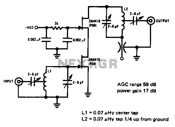
This 200 MHz JFET cascode circuit exhibits low cross-modulation, significant signal handling capability, no need for neutralization, and automatic gain control (AGC) managed by adjusting the bias of the upper cascode JFET. A specific requirement for this circuit is...
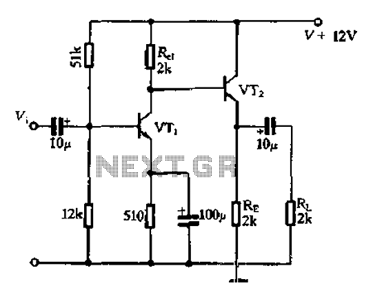
Available RC coupling between its two stages can also be directly coupled. This is in addition to the common-emitter total radio circuit configuration, which is widely used. Outside the previously described common-emitter circuit, a total group or common-emitter circuit...

Here is a design for a temporary lamp circuit that is very helpful in emergency situations or in any application where there is limited time to turn off the lamp. Simply press the push button to perform a quick...
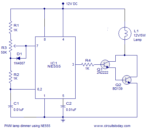
A simple PWM lamp dimmer using the NE555 timer IC. The 555 timer IC is configured as a variable duty cycle astable multivibrator to control the brightness of the lamp. The described circuit utilizes the NE555 timer IC, a versatile...
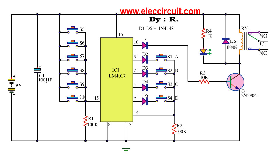
This key code switch circuit is an electronic circuit designed to replace conventional key switches, eliminating the need for physical key inserts. The key code switch circuit utilizes a microcontroller or a dedicated integrated circuit (IC) to interpret key codes entered...
For this test, an analog (non-digital) voltmeter is required. The distributor connector must remain intact. Small paper clips should be inserted into the backside of the distributor wire harness connector to establish contact with the terminals without damaging the...
Warning: include(partials/cookie-banner.php): Failed to open stream: Permission denied in /var/www/html/nextgr/view-circuit.php on line 713
Warning: include(): Failed opening 'partials/cookie-banner.php' for inclusion (include_path='.:/usr/share/php') in /var/www/html/nextgr/view-circuit.php on line 713