Coilgun Knowledgebase

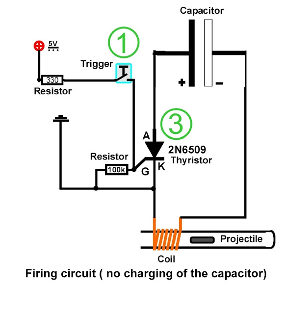
A coil is wound around a non-conductive tube, which serves as the barrel of the coilgun. The tube must be made from a non-conductive material, such as plastic, to prevent the coil's magnetic field from canceling itself out within the tube. The projectile must consist of ferromagnetic material, which reacts to magnetic fields. When a short current pulse flows through the coil from a charged capacitor and a switch, the projectile is drawn into the coil. If the current pulse concludes before the projectile reaches the center of the coil, it will exit the coil with increased velocity. Key challenges in coilgun design include winding an effective coil, selecting the appropriate voltage and capacitance, and precisely timing and positioning the projectile. A coil with more windings generates a stronger magnetic field; however, using excessively long and thin wire can lead to overheating or increased electrical resistance, which diminishes the current and weakens the magnetic field. Enhancing velocity can be achieved by adding additional stages, which involves incorporating more coils that must be triggered automatically as the projectile is already in motion. Commonly, light barriers are installed in front of the second stage to facilitate triggering. A schematic of the second stage light barrier trigger is provided, featuring the second stage, a light barrier, and a small screw that is pushed into the beam by the projectile's motion. A two-stage test rig has been constructed with multiple measurement devices to investigate the projectile's positioning relative to the coil, as well as the coil's characteristics, capacitance, voltage, and timing of the triggering mechanism. Numerous safety switches and control LEDs have been integrated for safety. The voltage range is from 0 to 400V, and one stage has a capacitance of 4400µF. Various projectiles of differing weights have been tested. A secondary measurement coil has been employed to record the indirect magnetic pulse generated by the first stage firing, while additional peaks are used for velocity measurement. Coilguns can be scaled for large applications, potentially functioning as mass drivers to launch payloads into orbit. They operate without moving parts, relying on invisible forces, and do not necessitate specialized construction techniques or unusual tools. The coilgun method can also be adapted to create levitrons, which are devices that hover without the influence of gravity.
The coilgun operates on the principle of electromagnetic induction, where a rapidly changing magnetic field is generated by the coil when current flows through it. This magnetic field interacts with the ferromagnetic projectile, inducing a force that propels the projectile along the barrel. The design of the coil itself is critical; it should be optimized in terms of the number of turns, wire gauge, and winding technique to maximize efficiency and minimize energy losses.
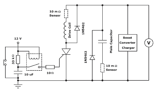
The capacitor used in the circuit serves as an energy reservoir, discharging its stored energy rapidly to create the necessary current pulse. The choice of capacitor is essential, as it must have a high capacitance and voltage rating to handle the energy demands of the coilgun. Additionally, the timing mechanism must be precise, often implemented using microcontrollers or comparator circuits that can detect the projectile's position and trigger the next stage of coils accordingly.
Safety considerations are paramount in coilgun design due to the high voltages and currents involved. Incorporating safety switches, fuses, and visual indicators such as LEDs helps to mitigate risks associated with accidental discharges or component failures. The use of measurement devices allows for real-time monitoring of the system's performance, providing valuable data for optimizing the coilgun's operation.
In summary, the coilgun represents a sophisticated application of electromagnetic principles, with potential for significant advancements in propulsion technology and other innovative applications such as magnetic levitation. The careful design and execution of each component within the system are crucial for achieving desired performance outcomes while ensuring safety and reliability.We have a coil wound over a non-conductive tube which is the coilgun`s barrel, of course. It has to be non conductive (plastic or something comparable) because otherwise the coil`s magnetic field would simply cancel out itself inside the tube. The projectile has to be made of a ferro magnetic material, that means stuff that reacts to magnetic fields.
If a short current pulse is passed through the coil via our charged capacitor and the switch, the projectile will be pulled into the coil. If the pulse ends before the projectile gets to the coil`s middle, it`ll leave with a gain in velocity.
The main difficulties with coilguns are winding an appropriate coil, finding the appropriate voltage and capacity and of course timing and positioning of the projectile. The more windings a coil has, the stronger is its magnetic field. But if you use too long and thin wire with your coilgun, either the wire will eventually burn through or the coil`s electric resistance will go up and lower the current and thus weaken the magnetic field.
Further increasing of the velocity is possible by adding more stages which means not more than adding more coils. These coils need to be triggered automatically since the projectile is already in motion and you`re not able to push the button at the right moment.
Many people use light barriers mounted in front of the second stage. Here`s a schematic of my second stage light barrier trigger (Ignore the safety switchtes and safety lights): You can see the second stage, a light barrier in front of it and a little screw which gets pushed (normally it would fly through by itself due to the first stage) into the beam. I built this two staged test rig with multiple measurment devices in order to learn more about positioning of the projectile in front of the coil, the coil itself, capacity and voltage and timed triggering.
There are a lot of safety switches and control Leds just because of safety matters. Voltage range is from 0-400V and one stage has a capacity of 4400uF. I used several projectiles of different heaviness. Due to a second measurement coil I was able to record the indirect magnetic pulse of the first stage firing. The other two peaks are for velocity measurement. Coilguns are scalable to very large applications, possibly as large as a mass driver to put payloads into orbit.
It has no moving parts thus there`s the magic of invisible forces at work. It requires no special construction techniques or unusual tools. The coilgun technique can also be used to build so called levitrons which are "no gravity hovering devices". 🔗 External reference
