
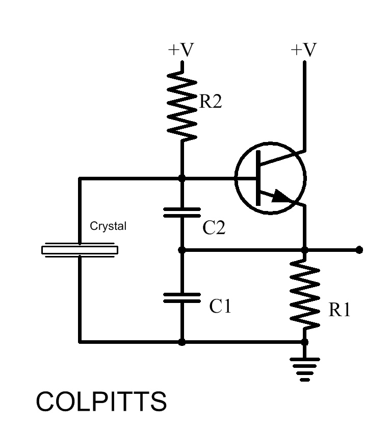
Colpitts Crystal Oscillator
To design a resonant circuit that achieves a specific frequency, the following steps can be employed:
1. **Determine the Desired Frequency**: Clearly define the target frequency (f) in hertz. This will serve as the basis for selecting the L and C values.
2. **Calculate Inductance and Capacitance**: Rearranging the resonant frequency formula allows for the calculation of either L or C when the other component is known. For example, if a specific inductance value is chosen, the corresponding capacitance can be calculated using C = 1 / (4π²f²L).
3. **Select Component Values**: Choose standard values for L and C that are readily available in the market. It is advisable to consider the tolerance and ratings of the components based on the application's requirements.
4. **Incorporate Resistance**: While resistance does not affect the resonant frequency directly, it is important to include it in the design to manage the circuit's bandwidth and quality factor (Q). The Q factor can be calculated using Q = f / Δf, where Δf is the bandwidth. Select R values that will provide the desired Q for the application.
5. **Simulation and Testing**: Before finalizing the design, it is prudent to simulate the circuit using software tools to verify the frequency response and make adjustments as necessary. Prototyping the circuit will also help in confirming the theoretical calculations.
By following these guidelines, a suitable combination of L, C, and R can be determined to achieve the desired frequency in a resonant circuit while ensuring optimal performance.Hey, Just wondering how to choose my L,C,R variables to achieve a desired frequency. Do I just choose any combination that yields X Mhz = 1 / ( 2pi *.. 🔗 External reference
Related Circuits
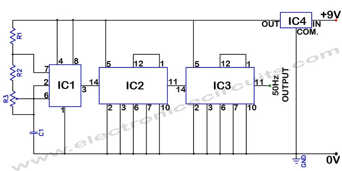
Accurate 50Hz Oscillator Circuit Using 555 and 7490. This circuit generates a 50Hz pulse. It consists of a 555 timer and two 7490 divide-by-ten counters. The circuit utilizes a 555 timer configured in astable mode to produce a square wave...
The Hartley Oscillator is a valuable circuit for generating high-quality sine wave signals in the RF range (30 kHz to 30 MHz). However, at the upper limits of this range and beyond, the Colpitts oscillator is typically favored. Both...
A feedback oscillator employs positive feedback to sustain oscillation. Essentially, an oscillator functions as an amplifier that incorporates feedback. A feedback oscillator is a critical component in various electronic applications, utilizing the principle of positive feedback to generate continuous waveforms....
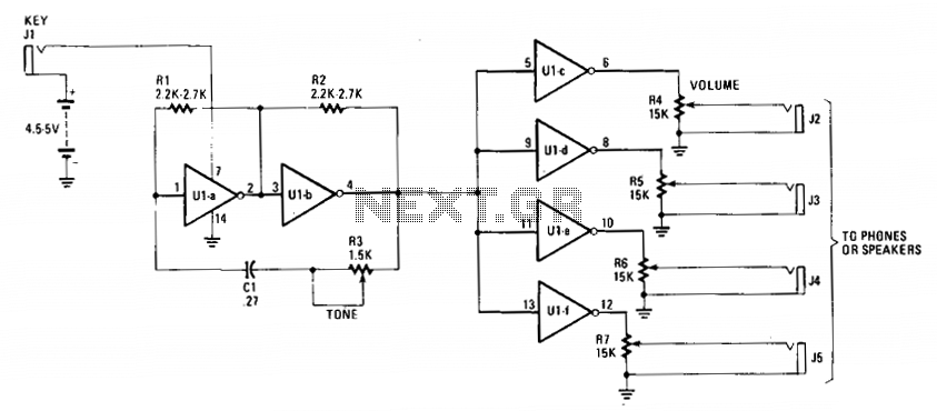
The cost-effective 7404 hex-inverter provides sufficient amplification to accommodate a broad spectrum of transducers. Engaging the switch completes the battery circuit, supplying four to five volts to the 7404. The bias for the first two inverter amplifiers (Ula and...
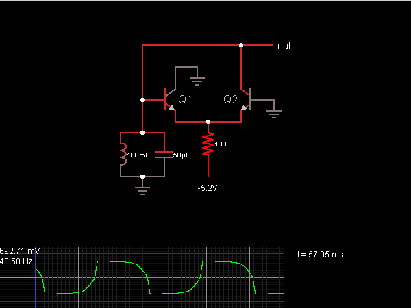
When the oscillator starts, Q2 is in a conducting state; the current flows from the capacitor, charging it until the voltage across it is sufficient to allow current to flow through the inductor. As the current through the inductor...
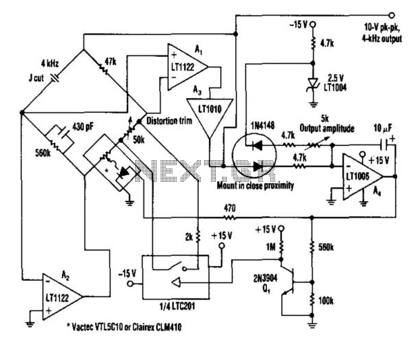
This oscillator utilizes a bridge circuit with an optoisolator functioning as a gain-control device. The resultant distortion can be maintained at 9 ppm (0.0009%) with appropriate adjustments. The oscillator circuit described operates using a bridge configuration, which is a common...