
Colpitts Oscillator Tutorial and Oscillator Design
The Colpitts oscillator is a type of electronic oscillator that utilizes a tank circuit composed of inductors and capacitors to produce sine wave signals. The fundamental operation of the Colpitts oscillator is based on the principles of resonance in LC circuits, where the energy oscillates between the inductor and capacitors at a specific frequency determined by their values.
The tank circuit typically consists of a single inductor (L) and two capacitors (C1 and C2) connected in series. The output frequency of the oscillator can be calculated using the formula:
\[ f = \frac{1}{2\pi \sqrt{L \cdot \frac{C1 \cdot C2}{C1 + C2}}} \]
In this configuration, the capacitors C1 and C2 form a voltage divider, which is crucial for the feedback mechanism that sustains oscillation. The inductor provides the necessary phase shift and energy storage required for the oscillation process.
The active component used in the Colpitts oscillator can be a transistor or an operational amplifier. The transistor is configured in a common emitter or common collector arrangement, providing the necessary gain to compensate for losses in the circuit. The feedback loop is established by connecting the output of the tank circuit back to the input of the transistor, ensuring that the oscillation continues.
One of the significant advantages of the Colpitts oscillator is its ability to generate stable frequencies with low distortion, making it suitable for various applications, including RF signal generation, audio synthesis, and clock generation in digital circuits. The design can be easily adjusted by changing the values of the capacitors and inductor, allowing for fine-tuning of the output frequency.
In summary, the Colpitts oscillator is a versatile and widely used circuit in electronics, leveraging the principles of LC resonance to produce reliable sine wave outputs. Its design simplicity and frequency stability make it an essential component in many electronic systems.Colpitts Oscillator Tutorial and the theory behind the design of the Colpitts Oscillator which uses a LC Oscillator tank circuit to generate sine waves.. 🔗 External reference
Related Circuits
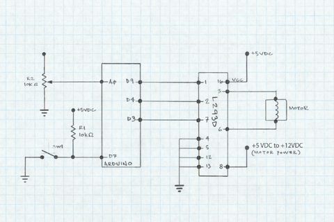
The L293D H-Bridge is utilized to operate a 12V DC motor with an Arduino. This H-Bridge facilitates the interfacing of the motor, which requires significantly more current and voltage than the output pins can provide. With minimal connections, it...

This design circuit functions as a sine wave oscillator, providing both sine and square wave outputs across a frequency range from below 20 Hz to above 20 KHz. The oscillation frequency can be easily adjusted by varying a single...
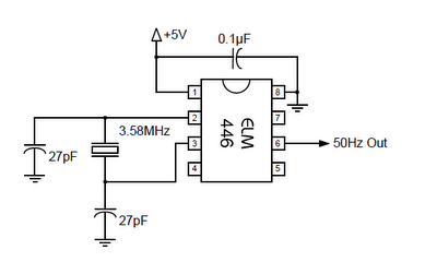
The ELM446 is an 8-pin digital divider integrated circuit that generates both 50Hz and 1Hz outputs from a common 3.58MHz NTSC colorburst crystal. The designer needs to supply only the crystal and two suitable loading capacitors, along with a...
This document discusses the advantages and disadvantages of various power supply technologies, along with the design considerations necessary for selecting and evaluating a mains transformer. It covers the pros and cons of external supplies, inrush current control, RF emissions...
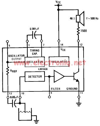
The LM1830 low-level detector can utilize an audio indication (speaker) or a visual indicator (LED - light-emitting diode) that activates when the level is too low. This low-level detector circuit generates a 500 Hz audio signal when the level...
An oscillator is a circuit that generates a frequency source such as a sine wave, square wave, or pulse train. It combines a frequency-sensitive circuit, like an LC circuit or a crystal, with a negative resistance typically provided by...