
Combinational circuits Encoder Decoder
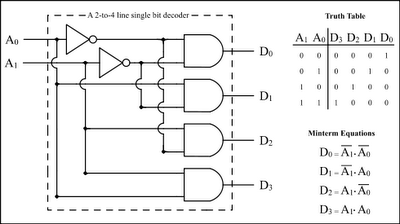
The encoder and decoder circuits play crucial roles in digital systems, particularly in data encoding and decoding processes. The decoder, operating on n-bit binary inputs, generates 2^n distinct outputs, which can be utilized in various applications such as memory address decoding, data multiplexing, and digital display systems. The enable signal is essential for controlling the circuit's operation, ensuring that the decoder only activates its outputs when required. This functionality is particularly useful in applications where multiple decoder circuits may be used in conjunction, allowing for selective activation based on system requirements.
The encoder, on the other hand, serves the purpose of compressing multiple input signals into a smaller number of output signals. In the case of an 8×3 encoder, it consolidates eight input lines into three output lines, effectively reducing the number of bits required to represent the input data. The outputs of the encoder represent the binary equivalent of the active input line, which is determined by the logic level of the inputs. This functionality is valuable in applications such as data transmission, where bandwidth conservation is essential.
Both circuits can be implemented using various logic gates, including AND, OR, and NOT gates, and can be designed to accommodate additional features such as priority encoding in encoders, where higher-priority inputs can override lower-priority ones. The design and implementation of these circuits require careful consideration of the desired functionality, input and output specifications, and the overall system architecture to ensure optimal performance in the intended application.The Encoder and Decoder are different kind ofcombinationalcircuits which are used to convert binary information to decimal, octal and hexa decimal andvice-versa. A decoder iscombinationalcircuitwhich is used for to convert n it binary information to 2n unique outputs.
so that a decoder circuit isused for to convert a binary information to de cimal, octal and hexa decimal. a decoder circuit is a variable circuit called as nxm decoder. The outputs are D0, D1, D2, D3, D4. The inputs are connected to 4 AND gates and derive Unique outputs. If we have Enable it will come along with input line. This is used to start the process of decoder circuit. Weather is Zero the inputs representing with xx called don`t care conditions. An encoder is a combinational circuit which is used to convert 2n inputs to n outputs. so that it is reverse operation of a decoder. it converts the decimal information to binary. In 8x3 encoder circuit consists 8 inputs called D0 to D7 and the outputs A0, A1, A2 the all the inputs connected to a specified OR gate to representing the binary equavalent of a specifed decimal. The outputs are as follows. 🔗 External reference
Related Circuits
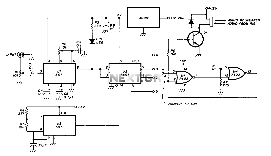
The Phase-Locked Loop (PLL) integrated circuit (U1) is configured with resistor R2 to achieve the desired tone frequency. An LED indicator is used to show when the PLL has locked onto the signal. To ensure proper lock-up, the signal...

Another application of the frequency-to-voltage converter (FVC) is the tone/frequency decoder. This circuit is designed to identify the frequency band of an oscillating signal. It is utilized in various applications, such as determining the frequency band in signals and...
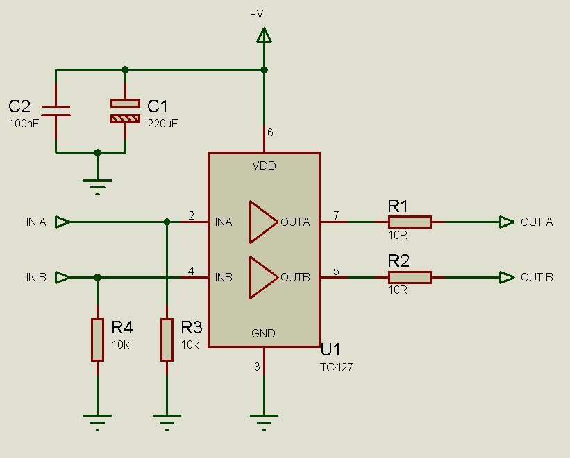
MOSFETs cannot simply be connected to the drive signal and expected to function correctly. Due to their construction, driving MOSFETs can be complex, particularly for beginners. Many users frequently seek assistance with MOSFET drive issues on various blogs, websites,...
This circuit is a digital panel meter (DPM) featuring an analog bar graph display and a 3.5-digit digital display. The ICL7107 is configured for 200mV input. The U4A operational amplifier (LF353) amplifies the 200mV full-scale input to the required...
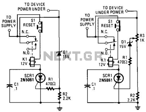
If circuits experience frequency overvoltage conditions, continually replacing blown fuses can become quite costly. This shutdown circuit addresses that issue by substituting the fuse with a relay and a low-current SCR. When the input voltage exceeds the threshold established...
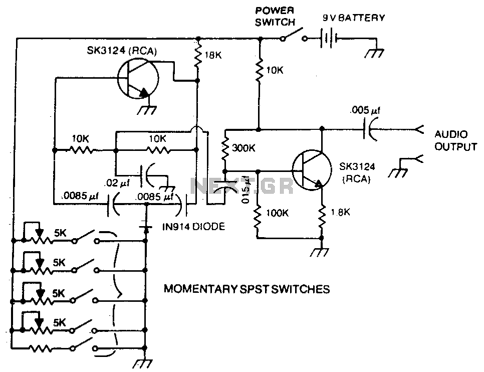
A basic twin-T circuit uses resistors to accurately set the frequency of the output tones, selected by pushbuttons. Momentary switches generate a tone only when the button is pressed. The twin-T oscillator circuit is a well-known electronic configuration used for...
Warning: include(partials/cookie-banner.php): Failed to open stream: Permission denied in /var/www/html/nextgr/view-circuit.php on line 713
Warning: include(): Failed opening 'partials/cookie-banner.php' for inclusion (include_path='.:/usr/share/php') in /var/www/html/nextgr/view-circuit.php on line 713