
Combustible gas alarm circuit
The combustible gas alarm circuit is designed to detect the presence of harmful combustible gases in the environment and alert users through an auditory signal. The core of the circuit involves a gas sensor that is sensitive to specific combustible gases. When the concentration of gas in the air rises above a predefined threshold, the sensor's resistance changes, leading to a corresponding change in the output voltage.
The multivibrator, constructed from NAND gates, serves as an oscillator that generates a square wave output when triggered by the sensor's output voltage. This square wave signal is essential for activating the audio output stage of the circuit. The audio output stage is composed of an amplification transistor (VT) and a speaker (BL), which together convert the electrical oscillations into audible sound.
In normal operating conditions, the gas sensors maintain a high resistance, which results in a low output voltage that keeps the multivibrator inactive. This ensures that the speaker remains silent, thereby conserving power and preventing false alarms. The circuit is designed to operate effectively within specific voltage ranges, and the adjustable resistor (Rz) allows for calibration of the sensor's sensitivity, ensuring accurate detection of gas concentrations.
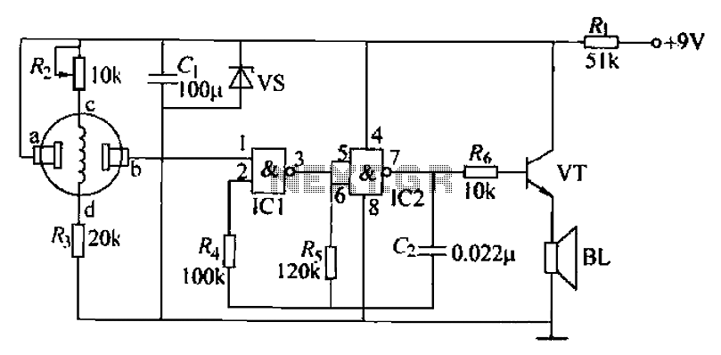
When the gas concentration exceeds the safe limit, the sensor output voltage increases, triggering the multivibrator. The resulting oscillation from the multivibrator is amplified by the transistor, which drives the speaker to produce a loud alarm, alerting individuals in the vicinity of the potential danger. This circuit is crucial for safety in residential and industrial environments where combustible gases may be present, providing an early warning to prevent accidents and ensure safety. Combustible gas alarm circuit is shown. Circuit by the gas sensor, multivibrator and audio output roads. Multivibrator integrated circuit by the NAND gate way inside two NAND g ates lu, IC2 and the external screen resistive and capacitive components. The audio output circuit consists of resistors Rs, audio amplification tube VT and speaker BL composition. (2) works when the room is no contaminated gas or combustible gas concentration within the allowable range (below the limit), the gas sensors a, b end the resistance between the larger, b-side (IC1s O feet) the output voltage is low, the multivibrator does not work, Jan microphone BL no sound.
When the combustible gas (gas or natural gas) leak, combustible gas concentration in the room exceeds the limit value, the b-side air tit sensor output voltage is higher than the switching voltage of IC1, multivibrator work from pin output oscillation lC signal. The VT signal after amplification, to promote the speaker microphone BL alarm. Adjust the resistance value Rz make gas sensors c, d between the voltage 4.5V.
Related Circuits
The objective is to transmit additional information through the distribution of articles. Please contact us via email at [email protected] within 15 days if there are any issues related to article content, copyright, or other concerns. Prompt action will be...

A circuit breaker is an automatically operated electrical switch designed to protect an electrical circuit from damage caused by overload or short circuit. Its basic function is to detect a fault condition and, by interrupting continuity, immediately discontinue electrical...
This circuit is designed to indicate when a plant requires watering. An LED flashes at a low frequency when the soil in the flower pot is excessively dry, and it turns off as the moisture level rises. The sensitivity...
Controlled by indoor and outdoor temperature, this circuit features a simple and highly reliable design. It is intended to control a heating system or central heating plan. The described circuit functions as a temperature control system, integrating both indoor and...

The circuit employs a field-effect transistor (FET) at the input of a Schmitt trigger, allowing the use of a low-value capacitor. The trigger, controlled by Q1 and O2, exhibits a hysteresis of approximately 3V, regulated by a 3V zener...
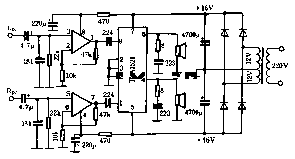
The first power amplifier circuit illustrated in Figure 5-88 utilizes the NE5532 operational amplifier, configured as a line amplifier, and features the TDA1521 power amplifier. This circuit operates with a dual power supply and eliminates the need for coupling...