Common Base Amplifier
1. Definition and Purpose
1.1 Definition and Purpose
The common base amplifier is one of the fundamental configurations used in bipolar junction transistor (BJT) amplifier circuits. In this topology, the input is fed into the emitter terminal, the output is taken from the collector terminal, and the base terminal serves as a common reference point for both input and output signals. This configuration is characterized by its unique behavior, particularly a low input impedance and high output impedance, making it suitable for specific applications requiring these parameters.
One of the core purposes of the common base amplifier is to provide signal amplification while maintaining a strict phase relationship between the input and output. The output signal is in phase with the input signal, differing from the common emitter configuration, which inverts the output signal. Thus, the common base amplifier is particularly useful in applications where phase integrity is critical, such as in RF (radio frequency) communications and some types of analog processing.
Amplification Characteristics
The common base amplifier provides a voltage gain that can be significant, dependent largely on the transconductance of the transistor and the load resistance in the collector. The gain (Av) can be approximated using the formula:
where RL is the load resistance, RE is the emitter resistance, and re is the intrinsic emitter resistance (ranging around 26 mV divided by the emitter current for silicon transistors). This result illustrates the significance of the load and emitter configuration in determining the overall amplification capability of the circuit.
Moreover, given the low input impedance offered by this configuration (typically a few hundred ohms), the common base amplifier is suitable for interfacing with low-impedance sources. This can be advantageous in scenarios where the relationship between output loading and source impedance is critical. Applications include:
- RF amplifiers, where the input source resistance is low and the output must drive high-impedance loads.
- Audio applications, particularly in signal conditioning stages where stable phase relationships are crucial.
- A common choice in high-frequency applications due to its high-frequency response and stability.
As we delve further into the specifics of the common base amplifier, it is crucial to notice that while it may not be as widely utilized as some other configurations like the common emitter amplifier, its unique properties make it indispensable in specialized applications. Understanding its operational principles deeply enhances the ability to integrate the common base amplifier in broader circuit designs, reinforcing the importance of learning this fundamental configuration in analog electronics.
1.2 Basic Operation Principle
In understanding the common base amplifier's operation, one must first appreciate its unique configuration. Unlike the common emitter or common collector amplifiers, the common base amplifier employs the base terminal as the common reference point for both input and output signals. This design results in certain distinctive features and operational principles that make it pertinent for specific applications. At its essence, the common base amplifier utilizes a bipolar junction transistor (BJT), emphasizing the flow of current through the collector and emitter terminals while maintaining the base at a fixed potential. This arrangement leads to an amplification scenario characterized by a high-frequency response and a low input impedance, making it particularly suitable for RF applications. To elucidate the operational principle mathematically, consider the BJT in the active region where it is biased appropriately. The input current, typically flowing into the emitter, is a critical factor that sets the stage for amplification. The relationship can be observed analytically as follows: 1. The input current, \(I_{E}\), at the emitter terminal serves as the dominant parameter of the circuit: $$ I_{C} \approx \alpha I_{E} $$ Here, \( \alpha \) represents the common base current gain (the ratio of collector current \(I_{C}\) to emitter current \(I_{E}\)) and is typically close to unity (around 0.95 to 0.99 in practical BJTs). 2. As the voltage across the base-emitter junction is very small (approximately 0.7V for silicon transistors), any change in emitter current translates directly to a change in collector current, but since \(I_{E}\) must be nearly equivalent to \(I_{C}\), it becomes evident that: $$ I_{C} = \alpha I_{E} $$ This equation highlights the virtue of utilizing \(I_{C}\) as a linear function of the input current \(I_{E}\), tapping into the transistor properties essential for high-frequency response. 3. To assess the voltage gain (\(A_{V}\)) of the device, we look at the output voltage \(V_{o}\) taken across the collector terminal concerning the emitter current: $$ A_{V} = \frac{V_{o}}{I_{E}R_{C}} $$ Here, \(R_{C}\) signifies the collector resistor. Thus, under the small-signal approximation conditions, the voltage gain can be expressed based on the incremental variations about a bias point, showcasing both operational stability and a high gain at specific operating frequencies. The output signal's characteristics in relation to the input provide insightful applications in contexts such as radio frequency amplification, where the capacity to drive low-impedance loads while maintaining signal integrity is critical. With its low input impedance, the common base amplifier is adept at matching high-frequency signals effectively, thereby ensuring minimal signal loss. In summary, the common base amplifier presents a unique operational principle grounded in current amplification through a fixed base reference. This not only highlights its practical applications in RF circuits but also showcases its fundamental role in managing signal integrity across low-impedance loads, marking it a vital configuration in the engineer's toolkit.1.3 Configuration and Biasing
In the analysis of a Common Base Amplifier (CBA), understanding its configuration and biasing is crucial for optimal performance. This section discusses the standard configuration of the CBA, how biasing influences the amplifier’s operation, and the practical implications of these factors.Common Base Amplifier Configuration
The Common Base configuration features the base terminal of the transistor as the common point for both the input and output signals. This serves to establish a stable operating point while allowing effective signal amplification. The input is applied between the emitter and base, while the output is taken across the collector and base. The CBA setup typically employs a BJT (Bipolar Junction Transistor) with the following terminals: - Emitter (E): Where the input signal is applied. - Base (B): Serving as the reference point for both input and output. - Collector (C): Output terminal where the amplified signal appears. The strength of the CBA derived from its configuration lies in its current gain, expressed as:Biasing Techniques
Operating a Common Base Amplifier requires appropriate biasing to ensure that it functions within a defined linear region. Biasing stabilizes the transistor's operating point, countering variations in transistor parameters due to temperature or manufacturing differences. There are principally two methods for biasing a Common Base amplifier: 1. Fixed Biasing: This involves connecting a resistor from the collector to the base. The biasing current is derived from the collector supply voltage, \(V_{CC}\), and the base-emitter voltage \(V_{BE}\). The fixed bias provides a simple approach but may lack stability against temperature variations. 2. Voltage Divider Biasing: This method utilizes two resistors to create a voltage divider network that significantly improves stability. The network feeds a stable voltage to the base, thereby conserving the transistor's quiescent point more effectively. The practical implementation of a voltage divider bias can establish the desired base voltage \(V_B\):Practical Applications
Common Base Amplifiers are extensively used in high-frequency applications such as RF amplifiers due to their ability to present low input impedance while offering high output impedance. Additionally, they are beneficial in applications requiring wide bandwidth, like in signal processing and telecommunications. Moreover, understanding the efficient biasing of a CBA ensures low distortion and maximizes linear operation, making it essential for precision analog signal amplification, as seen in audio and instrumentation technologies. In conclusion, the configuration and biasing techniques used in Common Base Amplifiers not only influence their performance but also dictate their suitability for various engineering applications. Mastering these concepts will empower engineers to design robust systems that meet precise operational requirements.2. Active Components Overview
2.1 Active Components Overview
The common base amplifier is a vital component in electronics, renowned for its ability to provide high frequency response with a low input impedance. To fully understand its operation, we need to first delve into the characteristics and role of active components within electronic circuits.
Active components are electrical components that require an external power source to function. Unlike passive components, which only store or dissipate energy, active components can amplify signals, generate oscillations, or perform switching functions. This distinguishing feature makes them indispensable in signal processing, power amplification, and electronic control systems.
Transistors as Fundamental Active Components
At the heart of the common base amplifier lies the transistor, a semiconductor device that operates as a switch or amplifier depending on the circuit configuration. The most commonly used transistors in amplifiers are bipolar junction transistors (BJTs) and field-effect transistors (FETs). Each type has unique characteristics that impart specific advantages and disadvantages when used in amplifying applications.
- Bipolar Junction Transistors (BJTs): These devices utilize both electron and hole charge carriers, thus requiring a small input current to control a larger output current. They are particularly well-suited for low-frequency applications due to their high gain and robust characteristics.
- Field-Effect Transistors (FETs): Unlike BJTs, FETs control current through an electric field, offering high input impedance and better suitability for high-frequency applications. They excel in low-noise performance and are commonly used in RF applications.
Understanding Operational Characteristics
The choice of an active component significantly affects the amplifier's performance. Parameters such as gain, bandwidth, and input and output impedance are crucial in determining an amplifier's effectiveness for a given application. For instance:
- Gain: Represents the amplification factor of the input signal. In the case of the common base amplifier, the voltage gain is relatively lower compared to the common emitter configuration but offers favorable input-output phase characteristics.
- Bandwidth: Refers to the range of frequencies over which the amplifier operates effectively. The common base amplifier, with its low input capacitance, generally provides a broader bandwidth compared to other configurations.
- Input and Output Impedance: Understanding these values helps in matching the amplifier to the source and load, ensuring maximum power transfer and minimizing signal distortion.
Practical Applications and Relevance
The practical relevance of the common base amplifier, and its underlying active components, lies in various fields such as:
- Radio Frequency (RF) Amplifiers: A common base amplifier is frequently used in RF amplifiers due to its wide bandwidth and stability, maximizing signal integrity in communication systems.
- Impedance Matching: By providing low input impedance and high output impedance, common base amplifiers are suitable for applications requiring signal matching between different stages of a circuit.
- Buffer Stages: These amplifiers can serve as buffer stages in mixed-signal processes, effectively isolating different sections of a circuit while preserving signal quality.
In conclusion, having a comprehensive understanding of the properties and functions of active components is essential for mastering the typical configurations of amplifiers like the common base. This knowledge not only prepares one for deeper exploration into complex circuit designs but also equips engineers and researchers with the tools necessary to innovate and optimize electronic systems.
2.2 Passive Components
In the realm of analog electronics, particularly when discussing amplifier configurations like the common base amplifier, it becomes essential to integrate passive components effectively. These components, which include resistors, capacitors, and inductors, play a crucial role in defining the performance characteristics of the amplifier and ultimately impact the overall circuit behavior. The common base configuration is distinct due to its unique input and output characteristics, especially when interfacing with passive elements. One of the primary advantages of this configuration is its low input impedance and high output impedance, making it a preferred choice in specific applications such as RF amplification, impedance buffering, and as a voltage follower in wide-bandwidth applications.Resistors
Resistors are fundamental passive components used in the common base amplifier to bias transistors properly and to control current levels. By implementing resistors in the input and output stages, engineers can influence the voltage gain and stability of the amplifier circuit. A significant aspect to consider is the biasing network. This network typically consists of more than one resistor that sets the operating point of the transistor. For instance, a voltage divider configuration might be employed to ensure the base of the transistor is at a suitable DC bias, thus facilitating linear signal amplification across varying input frequencies. To analyze the effects of biasing on the common base amplifier, let's derive the DC bias voltage: Consider a voltage divider consisting of two resistors, \(R_1\) and \(R_2\), connected to the supply voltage \(V_{CC}\). The voltage at the base \(V_B\) can be calculated as follows: $$ V_B = \frac{R_2}{R_1 + R_2} \times V_{CC} $$ This equation demonstrates how resistors in the biasing network dictate the base voltage, which is critical for ensuring that the transistor remains in its active region during operation.Capacitors
Capacitors are primarily used in common base amplifiers for coupling, decoupling, and frequency response shaping. Their role in coupling stages allows AC signals to pass through while blocking DC components, thus preserving the operating point of the transistor. In the context of coupling capacitors, consider the following relationship, which dictates the frequency response of a common base amplifier: $$ f_c = \frac{1}{2\pi RC} $$ Where \( f_c \) is the cutoff frequency, \( R \) represents the resistance in the circuit, and \( C \) represents the capacitance. This equation indicates that the selection of capacitors not only influences signal coupling but is also pivotal in defining the bandwidth of the amplifier. Additionally, decoupling capacitors are employed to stabilize power supply voltages by minimizing fluctuations caused by varying load conditions, which is essential for maintaining performance integrity in dynamic operational environments.Inductors
While not commonly a focal point in typical configuration discussions, inductors are occasionally employed in common base configurations, particularly for RF applications. Inductors can help filter out unwanted high-frequency noise and can also be part of resonant circuits to enhance frequency selectivity. In RF amplifiers, the use of inductors in conjunction with capacitors can highlight an LC circuit behavior, which is crucial for tuning purposes. The quality factor \( Q \) of these circuits can be expressed as follows: $$ Q = \frac{f_0}{\Delta f} $$ Where \( f_0 \) is the center frequency of the LC circuit, and \( \Delta f \) is the bandwidth, which also underlines the importance of choosing suitable values for inductors and capacitors.Real-World Applications
The integration of passive components in the common base amplifier not only showcases fundamental electronic principles but also allows for key applications across various fields. For instance: - RF Communication: Common base amplifiers are utilized in RF amplifiers due to their ability to handle high-frequency signals with minimal distortion. - Impedance Matching: The low input impedance and high output impedance make them ideal for connecting high-frequency sensors to low impedance loads without significant signal loss. - Medical Equipment: Devices such as ECG machines often require reliable amplification of tiny signals, where common base configurations can be paramount. In conclusion, understanding the role of passive components in the common base amplifier is essential for optimizing its performance in real-world applications. By carefully selecting and designing passive component values, engineers can fine-tune amplifier capabilities to meet the demands of sophisticated electronic systems.2.3 Circuit Design Techniques
When designing a Common Base (CB) amplifier, one must consider a variety of circuit design techniques to optimize performance, meet specific application requirements, and ensure stability. The CB configuration is less common than its Common Emitter (CE) counterpart; however, its unique characteristics can yield enhanced performance in specific scenarios. This section delves into the critical design considerations and techniques that are instrumental in creating an effective Common Base amplifier.Understanding the Common Base Configuration
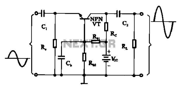
Before we dive into design techniques, it's essential to recap the operational basics of the Common Base configuration. In a CB amplifier, the input signal is applied to the emitter terminal, while the output is taken from the collector. This arrangement results in a high voltage gain and a low input impedance, making it particularly useful for high-frequency applications. To illustrate, consider a basic CB amplifier circuit. The transistor’s base is grounded, with the input signal connected to the emitter, and the output is derived from the collector. This results in a signal phase that is not inverted, providing a unique advantage in certain applications like RF amplification.Key Circuit Design Techniques
Effective design of a Common Base amplifier revolves around several structured techniques:1. Biasing Techniques
Biasing is critical for establishing proper operating points in any transistor circuit. For Common Base amplifiers, utilizing a fixed biasing technique is preferred, as it tends to be stable against variations in transistor parameters. A typical biasing network might include resistors connected from the power supply to the collector, ensuring that the transistor operates in its active region. It's also crucial to account for temperature stability and transistor parameter variations. Implementing techniques such as negative feedback can help maintain consistent performance by reducing distortion and enhancing linearity.2. Input and Output Impedance Matching
The low input impedance of Common Base amplifiers often necessitates careful design to match the impedance of preceding stages or sources. Using a source follower or buffer can relay the signal without significant loss. For output impedance matching, consider using a transformer or a resistor-capacitor (RC) combination to enhance power transfer to the next stage. Additionally, the use of high-frequency design techniques, such as L-C circuits, can be beneficial for achieving proper impedance matching at higher frequencies, ensuring that power is efficiently transferred without significant signal loss.3. Frequency Response Optimization
Common Base amplifiers excel at high-frequency applications. Therefore, it is critical to optimize the frequency response during design. This can be achieved by evaluating the transistor's cut-off frequency (fT), ensuring that it is well above the intended operating frequency. The frequency response also hinges on external capacitive components, like coupling capacitors placed at the input and output. Their values must be calculated to maintain a suitable low-frequency response, typically ensuring a cutoff point below the intended operational frequency range. A simple first-order filter analysis helps estimate these cutoff frequencies. In terms of high-frequency performance, utilizing bypass capacitors can effectively improve gain while maintaining stability across the desired bandwidth. This is a crucial aspect when aiming to avoid unwanted oscillations in high-frequency applications.4. Load Considerations
The load attached to a Common Base amplifier significantly influences its overall performance. When determining load values, consider the desired gain and the output impedance of the amplifier stage. The relationship can be enhanced by employing a load resistor that optimizes power output while ensuring the transistor remains in its active region. Simulation tools like SPICE can assist in virtual prototyping, allowing for intricate load calculations that can accommodate real-world component tolerances. Incorporating this sort of analysis can provide insights into non-ideal behaviors before physical implementation.5. Thermal Management
Thermal stability is often overlooked but is essential in high-power applications. The efficiency and performance of a Common Base amplifier can degrade due to thermal runaway. It is prudent to implement thermal management techniques, such as heat sinks or ventilation, especially when the amplifier operates in high-temperature environments. The influence of temperature can also be mitigated through careful selection of transistors with lower thermal coefficients or by incorporating thermal feedback circuits to maintain consistent operation.Real-World Applications
Common Base amplifiers see extensive use in RF communication systems, video signal transmission, and as impedance matching stages in audio systems. Their ability to handle higher frequencies and deliver low noise characteristics makes them suitable for these applications. In summary, the design of a Common Base amplifier can be complex, necessitating a comprehensive approach that considers biasing, impedance matching, frequency response, load influences, and thermal management. Successful implementation hinges on understanding these design techniques, which collectively contribute to the robust performance needed in high-fidelity electronic systems.3. Voltage Gain
3.1 Voltage Gain
The common base amplifier is a foundational topic in electronics, especially in applications that require high-frequency response and low input impedance. One of its key characteristics is the voltage gain, which plays a critical role in different amplification scenarios.
To understand the voltage gain of a common base amplifier, it's integral to dissect its operation. The voltage gain is defined as the ratio of the output voltage change to the input voltage change. In mathematical terms, this is expressed as:
Where \( V_{out} \) is the voltage at the output terminal and \( V_{in} \) is the voltage at the input terminal. In the context of the common base configuration, the input is typically taken from the emitter and the output across the collector.
Derivation of Voltage Gain
Let’s delve deeper into the derivation of this gain. In a common base amplifier, we consider small signal parameters. The input voltage \( V_{in} \) applies to the emitter, and the output voltage \( V_{out} \) can be taken from the collector. The transistor can be modeled using its hybrid-pi model for small signal analysis.
The collector current \( I_C \) can be approximated by the emitter current \( I_E \) due to the transistor action, given by:
Here, \( \alpha \) is the common base current gain, which is typically close to 1. Therefore, the relationship between the voltages can be derived from Kirchhoff's law. The change in output voltage is affected by the load resistor \( R_L \) connected to the collector:
Substituting for \( I_C \) gives:
The emitter current itself can be linked to the input voltage \( V_{in} \) as:
Considering \( V_{BE} \) (the base-emitter voltage) is relatively constant for small signal variations, we can express the voltage gain as:
This equation shows that the voltage gain in a common base amplifier is influenced primarily by the load resistance \( R_L \) and the emitter resistance \( R_E \). The negative sign indicates a phase inversion typical of amplifier circuits.
Practical Relevance
The common base amplifier's voltage gain property is particularly useful in high-frequency applications, such as RF amplifiers. Devices operating within the radio frequency spectrum require amplifiers that demonstrate consistent gain without significant bandwidth limitations. The design of such amplifiers often requires careful selection of components to maintain performance.
Moreover, understanding and manipulating the voltage gain allows engineers to tailor amplifiers for specific applications, ensuring optimal functionality in communication systems, medical devices, and various sensing applications. Given its low input impedance and high output impedance, the common base amplifier effectively interfaces with other high-impedance stages, making it invaluable in cascade amplifier designs.
3.2 Current Gain
In a common base amplifier configuration, understanding the concept of current gain is pivotal to appreciating its performance characteristics. Unlike common emitter amplifiers, where voltage gain is typically highlighted, the current gain in a common base amplifier holds significant relevance, primarily due to the unique input-output relationship observed in this setup.
The current gain, often denoted as α (alpha), reflects the ratio of the output current to the input current. Specifically, it is defined as:
where IC represents the collector current and IE denotes the emitter current. A key aspect of the common base configuration is that the base terminal is common to both the input and output circuits, leading to specific interactions between these currents.
The Mechanisms Behind Current Gain
To gain a deeper understanding of current gain, we must recognize the common base amplifier's operation. When an input signal is applied at the emitter terminal, it causes a change in the emitter current. Given the physical structure of the transistor, this change induces a corresponding change in the collector current, albeit with some distinctions from the emitter current.
It's important to note that in a well-designed common base amplifier, the value of α typically approaches unity (1), ranging between 0 and 1. This indicates that nearly all of the emitter current flows into the collector, leading to high current gain. The relationship can also be expressed in terms of the collector-emitter currents:
From this, it can be understood that high α values signify efficient amplification, which is crucial in RF applications where the common base amplifier is preferred for its ability to handle high-frequency signals effectively.
Real-World Applications
The performance characteristics of common base amplifiers make them suitable for several applications, particularly in radio frequency (RF) circuits. Their superior ability to manage high-frequency signals without significant distortion or attenuation has made them invaluable in:
- RF Amplifiers: Used primarily in communication systems to amplify weak signals.
- Impedance Matching: The common base configuration provides excellent input and output impedance performance, facilitating integration within diverse circuit designs.
- Signal Conditioning: Leveraging the properties of α, common base amplifiers aid in fine-tuning signal levels, thereby enhancing overall system performance.
In summary, the current gain in a common base amplifier is an essential parameter that reflects the efficiency with which it can amplify currents. Its fundamentally intuitive relationship between input and output currents, alongside practical applications in RF technology, underscores its significance in the broader field of electronics.
3.3 Input and Output Impedance
The common base amplifier configuration exhibits unique characteristics in terms of input and output impedance, which are crucial for its functionality and integration into electronic systems. Understanding these parameters not only delineates its behavior but also provides insight into its appropriateness for specific applications in signal processing and communication systems.Understanding Input Impedance
In a common base amplifier, the input signal is applied to the emitter terminal, while the base terminal is typically connected to a reference voltage or AC ground. This configuration leads to a very low input impedance, often resulting from the transistor's intrinsic properties. Specifically, in a bipolar junction transistor (BJT), the input impedance (\(Z_{in}\)) can be approximated by:Output Impedance Characteristics
Conversely, the output impedance of a common base amplifier is relatively high. The output is taken from the collector, and the impedance here can be represented as:Practical Implications and Applications
The low input and high output impedance traits of the common base amplifier afford it particular utility in RF applications, such as in radio transmitter circuits and broadband amplifiers. The ability to drive low impedance sources while presenting a significant buffering capability to high impedance loads makes it an ideal choice within these domains. Furthermore, engineers can leverage these impedance characteristics to enhance operational effectiveness in integrated circuits and communication systems, further illustrating the relevance of understanding input and output impedance in circuit design. The design of filters, oscillators, and matching networks often relies on the interplay of these impedance characteristics. In summary, a deep understanding of the input and output impedance of the common base amplifier not only sheds light on its operational principles but also empowers engineers to craft effective solutions in complex signal processing scenarios. Thus, mastery of these concepts is integral to the design and application of analog electronic systems.3.4 Frequency Response
The frequency response of a common base amplifier is fundamental to understanding its performance in both low-frequency and high-frequency applications. As this amplifier configuration is characterized by its ability to provide low input impedance and high output impedance, it plays a crucial role in various electronic circuits such as RF amplifiers and certain audio applications. To conceptualize the frequency response, we first need to analyze how the amplifier behaves as the frequency of the input signal varies. The behavior is determined by the reactive components within the circuit—specifically, capacitors and inductors—that influence the gain at different frequencies. In the common base configuration, the input signal is applied to the emitter, while the output is taken from the collector. This configuration exhibits a unique frequency response profile, primarily influenced by the coupling capacitors and any bypass capacitors that are present.Low-Frequency Response
At low frequencies, the coupling capacitors (often used to block DC and allow AC signals) exhibit high reactance. This is expressed mathematically as: $$X_C = \frac{1}{2\pi f C}$$ where \(X_C\) is the reactance, \(f\) is the frequency, and \(C\) is the capacitance. As frequency decreases, \(X_C\) increases, leading to attenuation of the input signal. This results in reduced gain in the low-frequency region—known as the lower cutoff frequency \(f_L\). To find \(f_L\), we can typically use the following relationship:High-Frequency Response
As we move toward higher frequencies, another significant phenomenon occurs: the internal capacitances of the transistor, especially the base-collector capacitance \(C_{bc}\) and base-emitter capacitance \(C_{be}\), become relevant. These capacitances create additional reactive paths for the signal at high frequencies, leading to a phenomenon called "Miller effect," where the effective capacitance gets multiplied by the gain of the amplifier. The cutoff frequency for the high-frequency roll-off, \(f_H\), can be approximated as:Overall Frequency Response Characteristics
In summary, the frequency response of a common base amplifier can be described by a bandpass characteristic, with defined lower and upper cutoff frequencies. As a result, the amplifier operates optimally within this band, delivering significant voltage gain, which can be visualized through a Bode plot. A typical Bode plot will feature: - A flat response within the passband, - A downward slope below \(f_L\) indicating gain loss, - Another downward slope above \(f_H\) due to the influence of capacitance. This specific dependency on frequency makes the common base amplifier suitable for applications where high-frequency operation is critical, including RF signal processing and impedance matching. Understanding the frequency response of the common base amplifier not only aids in the effective design of electronic circuits but also contributes to better performance in real-world applications, reinforcing the significance of careful selection of component values to tailor the amplifier to meet specific needs. Such characteristics make the common base amplifier a valued component in modern electronics, especially within communications and high-speed digital systems.4. RF Amplifiers
4.1 RF Amplifiers
The common base amplifier configuration is particularly well-suited for applications involving radio frequency (RF) amplification. As an advanced reader, you will appreciate the unique characteristics of RF amplifiers that stem from the common base arrangement, including low input impedance, high output impedance, and a notable capacity for wide bandwidth operation.
Understanding the role of RF amplifiers in various communication systems is essential, as they serve to amplify weak signals received from antennas, while minimizing noise and distortion. This is especially crucial in applications deploying amplitude modulation (AM) and frequency modulation (FM). With the increasing demand for efficient and high-performance wireless communication systems, RF amplifiers are continually being refined and optimized.
Fundamentals of RF Amplification
The common base amplifier operates with its input connected to the emitter terminal, while the output is taken from the collector. This arrangement results in a configuration that is particularly beneficial for RF applications due to the following aspects:
- Low Input Impedance: Typically, the input impedance is approximately equal to the intrinsic emitter resistance, which helps to match the impedance of the source signal. This low impedance is advantageous for coupling with antennas.
- High Output Impedance: The output impedance of the common base configuration is high, which allows effective voltage transfer to subsequently connected circuitry, maximizing power efficiency.
- High Gain and Bandwidth: The common base amplifier exhibits excellent high-frequency response because it avoids phase shifts that frequently impact common emitter configurations.
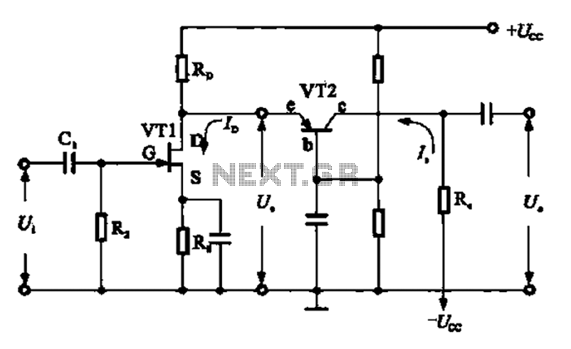
The diagrammatic representation of a common base amplifier facilitates visual understanding. Here, two key parameter definitions will aid in grasping the amplifier's functionality:
- Transconductance (gm): This is defined as the change in the output current divided by the change in input voltage. Mathematically, it can be represented as:
- Voltage Gain (AV): Defined as the ratio of output voltage to input voltage, the voltage gain in a common base amplifier is determined as follows:
where \( \beta \) is the current gain (typically around one for this configuration) and \( R_C \) is the load resistance connected to the collector. The voltage gain in this configuration is relatively constant over a wide range of frequencies, thus emphasizing its effectiveness in RF applications.
Real-World Applications
The practical implementation of common base RF amplifiers spans numerous fields, including:
- Television Transmitters: Often employed as first-stage amplifiers in transmission systems to boost weak signals.
- Cellular Networks: Vital in enhancing signals for mobile communications, ensuring greater reliability and coverage.
- RFID Systems: Effectively amplify signals in RFID tags, making them operational over various distances.
In summary, the common base amplifier significantly contributes to the field of RF amplification, characterized by efficient signal processing capabilities. Through an understanding of its practical benefits and theoretical foundation, engineers and researchers can leverage this knowledge to develop advanced communication technologies.
4.2 Impedance Matching
In the context of the common base amplifier, impedance matching is a pivotal consideration for optimizing performance when interfacing with other circuit components. A common base amplifier is characterized by its unique configuration which provides a low input impedance and a high output impedance. This attribute presents distinctive challenges and opportunities for impedance matching, a phenomenon crucial for maximizing signal transfer and minimizing reflection in communication systems and other electronic applications.
To appreciate the significance of impedance matching in a common base amplifier, it's vital to understand the basic parameters involved. The amplifier's input impedance \( Z_{in} \) typically ranges from 10 to 100 ohms, depending on the transistor characteristics and biasing conditions. Conversely, the output impedance \( Z_{out} \) tends to be substantially higher, often in the range of several kilo-ohms. This disparity in impedance values can lead to suboptimal performance when connecting the amplifier to other circuit stages, such as mixers or load devices, which usually require specific impedance levels for effective operation.
Maximizing Power Transfer
The principle of maximum power transfer can be a guiding philosophy when addressing impedance matching. To achieve maximum power transfer, the output impedance of the amplifier should be equal to the input impedance of the next stage of the circuit. This implies that for a common base stage interfacing with a subsequent load, engineers may require the implementation of a matching network.
An efficient impedance matching network often utilizes either transformers or reactive components such as capacitors and inductors to bridge the impedance gap between stages. For example, a transformer can provide a means for both step-up and step-down impedance transformation, creating the necessary conditions for power transfer without significant signal loss.
Reactive Matching Techniques
Beyond passive components, reactive matching techniques can be employed, wherein the net reactance of a circuit is adjusted to achieve the desired impedance. The use of LC networks—either in series or parallel configurations—can significantly enhance performance. In many cases, inductors can be used to compensate for capacitive loads, thereby optimizing the overall impedance seen by the common base amplifier.
Mathematically, the matching network can be characterized by two conditions: the real part of the load must match the amplifier's output impedance, and the imaginary part of the input impedance must be zero. By utilizing complex impedance notation, we may represent this as:
where \( R_{L} \) is the load resistance, and \( jX_{L} \) is the load reactance. To achieve matching, the following condition must hold:
Real-World Applications
In practical applications, common base amplifiers with effectively matched impedance are utilized in RF (radio frequency) applications, such as in front-end circuits of receivers, where low noise and high frequency response are critical. The choice of impedance transformation techniques directly influences the performance metrics, such as bandwidth and efficiency, which are essential in tightly regulated communication systems. Furthermore, understanding the impedance characteristics aids in the design of filters, mixers, and other components where signal integrity is paramount.
In summary, effectively matching impedance in common base amplifiers is essential for efficient signal transfer and performance optimization. Leveraging both passive components and reactive techniques enables engineers to tailor configurations suited to specific application requirements, thereby ensuring optimal functionality in advanced electronic systems.
4.3 Signal Processing
Signal processing in the context of common base amplifiers (CBAs) is a critical area that merges both analog and digital techniques to improve the performance and functionality of electronic circuits. A common base amplifier, while less prevalent than common emitter configurations, showcases unique advantages in specific applications, especially when dealing with high-frequency signals.
Understanding Common Base Amplifiers
To appreciate the role of signal processing in CBAs, one must first recognize their fundamental characteristics. In a common base configuration, the input signal is applied to the emitter terminal, while the output is taken from the collector. This results in a high output impedance and low input impedance, making the common base amplifier suitable for applications such as RF amplification, where these characteristics are essential.
The Role of Frequency Response
Signal processing in CBAs largely revolves around their frequency response, which is primarily influenced by capacitive and resistive elements in the circuit. The frequency response can be modeled using Bode plots, providing a visual representation of gain versus frequency. The key is to ensure that the amplifier remains in its optimal operational range without introducing significant distortion.
Mathematically, the frequency response can be articulated through the transfer function, \( H(s) \), which describes how the output signal varies respecto to the input signal over a range of frequencies. This can be derived as follows:
Through appropriate manipulation of the circuit parameters, such as the emitter resistor and collector load, one can optimize the bandwidth and gain. Generally, one observes that:
Where \( g_m \) is the transconductance and \( R_{C} \) and \( R_{E} \) are the collector and emitter resistances, respectively. Balancing these components allows engineers to fine-tune performance based on the application requirements.
Practical Applications of Signal Processing
Common base amplifiers excel in specific scenarios such as:
- Radio Frequency Applications: Due to their low input impedance, they can interface directly with RF sources and antennas, making them invaluable in communication systems.
- Impedance Buffering: Their inherent ability to handle impedance matching makes them useful in situations where impedance transformation is necessary.
- High-Speed Applications: The common base configuration provides a quick response to rapidly changing input signals, suitable for high-speed waveform processing.
The integration of filtering techniques in conjunction with CBAs significantly enhances signal integrity. For instance, combining a common base amplifier with low-pass or band-pass filters can help to mitigate unwanted high-frequency noise while preserving desired signal components.
As we consider the future of signal processing in common base configurations, research into CMOS technology and gallium nitride (GaN) offers promising directions. These materials allow for higher frequency operation and improved efficiency, aligning well with the increasing demand for compact and high-performance amplifiers in both consumer electronics and telecommunications.
Conclusion
In conclusion, the potential of common base amplifiers in signal processing environments is significant and multifaceted. By understanding and optimizing their frequency response characteristics, engineers can leverage their unique advantages in applications where traditional configurations may fall short. As technology progresses, the integration of advanced materials and signal processing techniques promises to further enhance the utility of CBAs in modern electronic systems.
5. Common Issues and Solutions
5.1 Common Issues and Solutions
When engaging with Common Base Amplifier (CBA) circuits, engineers and researchers may encounter various challenges ranging from stability issues to performance limitations. Understanding these common issues involves a foundational grasp of both circuit theory and practical electronics. Below, we dissect prevalent problems and propose effective solutions to enhance performance and reliability in CBA applications.Stability Issues
CBA configurations can suffer from instability due to feedback factors. Particularly, the relationship between the input and output resistance can induce unwanted oscillations. This instability arises when the gain of the amplifier approaches or exceeds unity. To address this, introducing a feedback network can help stabilize the gain. A negative feedback loop effectively reduces gain fluctuations, thus fostering stability. Additionally, implementing bypass capacitors across emitter resistors can mitigate high-frequency oscillations, allowing for better frequency response and augmented stability.Input and Output Impedance Matching
In many instances, impedance mismatch can degrade performance, resulting in signal loss. The input impedance of a CBA is typically lower compared to other amplifier configurations, leading to challenges in interfacing with high-impedance sources. To counteract this issue, consider utilizing a matching network that consists of transformer-based couplings or resistive networks. These can effectively bridge impedance gaps, ensuring efficient power transfer and maximizing signal integrity.Gain Limitations
While the CBA is known for its fixed gain characteristics, users often encounter scenarios where gain falls short of expectations, particularly in high-frequency applications. This attenuation can be traced back to various factors, such as parasitic capacitances that influence the frequency response. Improving gain can be achieved through several avenues. Firstly, one can implement the use of transistor models with better high-frequency response, specifically designed to reduce parasitic capacitance effects. Secondly, optimizing the passive components in the circuit can help mitigate bandwidth limitations.Thermal and Noise Issues
Thermal instability is another critical problem often overlooked in CBA configurations. Transistor junction temperature variations can significantly influence performance, leading to distortion and drift in output signals. To enhance thermal management, utilize heat sinks and ensure proper ventilation in designs. Furthermore, biasing the transistor within the optimal operating region will minimize thermal runaway. Noise is an inherent issue in any amplifier circuit. In the CBA, the noise figure can be affected by the choice of resistor values, biasing configurations, and the intrinsic noise of the transistor itself. To mitigate noise, using high-quality, low-noise components and optimizing layout to reduce coupling with external noise sources is essential.Practical Applications and Testing
Evaluating the performance of a CBA often necessitates extensive testing and simulation under various conditions. Utilizing simulation software, such as SPICE, allows for thorough analysis of how changes in parameters affect performance metrics. During practical applications—such as RF transmission lines or analog signal processing—implement regular tests to capture any instabilities or deviations from expected performance. By proactively addressing these common issues using the mentioned solutions, engineers and researchers can optimize the functionality of Common Base Amplifiers, ensuring they meet the stringent demands of modern electronics applications.5.2 Analyzing Circuit Behavior
The common base amplifier is a unique configuration that often finds its place in high-frequency applications due to its distinctive properties. In this section, we will delve into analyzing the behavior of the common base amplifier, which will provide insights into its operating principles, gain characteristics, and practical applications.
Understanding Circuit Configuration
A common base amplifier consists of a bipolar junction transistor (BJT) where the base terminal is common to both the input and output circuitry. The input is applied to the emitter, while the output is taken from the collector. This configuration offers a low input impedance and a high output impedance, making it suitable for specific signal amplification tasks.
Input and Output Characteristics
To better understand the amplifier's behavior, let us begin with the relationship between input and output signals. The common base amplifier does not provide voltage gain; instead, it provides current gain. This characteristic is essential for applications requiring impedance matching or current amplification. The voltage gain (Av) can be analyzed as:
Here, gm is the transconductance parameter, representing the ability of the transistor to control current flow through a change in input voltage. For small-signal analysis, the transconductance is given by:
Where IC is the collector current and VT is the thermal voltage (approximately 26 mV at room temperature). The resistors RC and RE represent the load and emitter resistance, respectively. This relationship underscores that even with no voltage gain, we can achieve current gain across the circuit.
Frequency Response and Stability
The common base amplifier is noted for its excellent linearity at high frequencies, as it exhibits minimal phase shift between the input and output signals. Its frequency response can be modeled through the input impedance (Zin), which is predominantly determined by the emitter resistance:
Practically, the input impedance is low (typically in the range of a few hundred ohms), allowing it to source large currents from a low impedance source. This feature makes the common base amplifier a great choice for RF applications, where signal integrity across various impedance levels is crucial.
Real-World Applications
Common base amplifiers are widely used in applications such as:
- RF Signal Amplification: Enhancing weak radio frequency signals in communication devices.
- Impedance Matching: Serving as a critical buffer between circuits of varying impedances.
- Wideband Amplifiers: Offering broad frequency response in high-speed circuitry.
In conclusion, the behavior of common base amplifiers can be effectively analyzed through their input and output characteristics, combined with their high-frequency performance. This understanding not only aids in finding appropriate applications but also influences the design of circuits requiring specific amplifying properties.
5.3 Simulation Tools
In the realm of electronic circuit design, particularly concerning amplifiers such as the common base amplifier, simulation tools are paramount. They allow engineers to visualize and analyze circuit behavior under varying conditions without the need for physical prototypes. This saves time and resources, providing insights that enhance understanding and improvement of circuit designs.
Simulation tools serve multiple purposes, including component modeling, frequency response analysis, and transient response analysis. They can help predict the performance metrics of amplifiers, such as voltage gain, input and output resistance, and bandwidth, which are critical for optimizing circuit functionality in real-world applications.
Popular Simulation Tools for Common Base Amplifiers
Several robust software packages exist, each catering to different levels of expertise and application needs. The choice of tool often depends on the complexity of the design and user familiarity. Below are some popular simulation tools used extensively in the industry and academia:
- Cadence Allegro PCB Designer — A comprehensive package for PCB design that incorporates robust simulation capabilities for evaluating amplifier performance and ensuring reliability.
- Altair Flux — This tool specializes in circuit simulation and electromagnetic analysis, providing in-depth insights into the behavior of analog circuits, including amplifiers.
- TINA-TI — A powerful circuit simulation tool from Texas Instruments, focusing on analog and mixed circuits, making it ideal for evaluating common base amplifiers.
- Ngspice — An open-source mixed-level circuit simulator for circuit analysis, integrating seamlessly with other software for comprehensive analysis.
- Micro-Cap — A versatile tool for simulating electronic circuits, including advanced features for analyzing amplifier characteristics in varied scenarios.
- Asimptote — A sophisticated circuit simulator ideal for high-frequency and RF circuit designs, allowing users to model and analyze common base amplifier circuits effectively.
- PSpice — A comprehensive simulation program for the analysis of analog and mixed-signal circuits, widely used in both academic and professional settings.
- Qucs — An open-source circuit simulator offering a graphical interface and a wide range of simulation capabilities, suitable for evaluating many types of amplifiers.
Each of these tools offers unique features and serves different needs, from comprehensive frequency domain analysis to fast transient response studies. Selection of the right tool enhances not only design efficiency but also the accuracy of predictions regarding amplifier performance in real-world applications.
6. Recommended Textbooks
6.1 Recommended Textbooks
- The Art of Electronics — This comprehensive textbook by Paul Horowitz and Winfield Hill is vital for professionals dealing with electronics. It covers analog and digital electronics and discusses amplifier configurations, including the common base amplifier, with ample practical examples.
- Electronic Devices and Circuit Theory — Authored by Robert L. Boylestad and Louis Nashelsky, this book delves into semiconductor fundamentals and amplifier configurations, offering detailed explanations and illustrations, making it indispensable for deep understanding.
- Microelectronic Circuits: Analysis and Design — Gavriel Salomon's book explores the structure of electronic circuits, including common base amplifiers, with rigorous mathematical analysis, providing engineers with deep insights into circuit behavior.
- Microelectronics: Circuit Analysis and Design — By Donald A. Neamen, this text presents the art of microelectronics, offering comprehensive discussions on various amplifier models, bridging the gap between theory and practical circuit implementation.
- Electronics: Circuits and Systems — A textbook providing a balanced coverage of electronic principles and applications. Peter Singer offers clarity on less intuitive topics like the common base amplifier through detailed examples and problem sets.
- Electronic Circuits: Theory and Applications — Authored by Jim Yeo, this book combines theoretical concepts with in-depth practical applications, including detailed analysis of amplifier types like the common base amplifier, aiding practical comprehension.
- Integrated Electronics: Analog and Digital Circuits and Systems — Jacob Millman's work provides robust coverage of both analog and digital circuits. Key concepts such as the common base amplifier are explored in detail, making it a vital resource for electronics professionals.
6.2 Research Papers
- Common Base Amplifier Characteristics — This IEEE paper provides a comprehensive analysis of the common base amplifier, detailing its unique characteristics, impedance matching capabilities, and typical applications in high-frequency circuits.
- Performance Analysis of Common Base Amplifiers in RF Applications — A detailed study published in ScienceDirect, focusing on the performance enhancements of common base amplifiers for radio frequency (RF) applications, highlighting their low-input and high-output impedance properties.
- Design Techniques for Common Base Amplifiers — Explore innovative design techniques for optimizing the efficiency and stability of common base amplifiers, including case studies and simulation results on various circuit topologies.
- Advanced Bipolar Junction Transistor Amplifier Models — This Online Library resource delves into advanced BJT models, including the common base configuration, focusing on enhancing linearity and bandwidth in complex electronic systems.
- Improving Noise Performance in Common Base Amplifiers — This Springer journal article investigates methods to reduce noise levels in common base amplifiers, making them more suitable for sensitive and precise electronic applications.
- Common-Base Gain Amplification Techniques — An in-depth ResearchGate publication on various techniques to amplify gain in common base configurations, emphasizing their crucial role in high-frequency signal processing.
- Transistor-Based Amplifier Innovations and Challenges — SAGE Journals presents cutting-edge innovations and challenges in transistor-based amplifiers, including the common base variant, focusing on strategies to overcome frequency and stability issues.
6.3 Online Resources
- Electronics Tutorials: Amplifier Classes — This comprehensive tutorial explores different amplifier classes, including common base amplifier circuits. It offers insights into design principles, advantages, and challenges for advanced learners.
- Analog Devices: Understanding BJT Amplifiers — A detailed article from Analog Devices discussing the theory and real-world applications of BJT-based amplifiers, including common base configurations.
- Texas Instruments: Basics of Low Noise Amplifiers — This document offers a perspective on designing low noise amplifiers, with sections dedicated to the unique features of common base designs.
- Circuits Today: Common Base Amplifier Tutorial — A highly informative guide detailing the functioning, characteristics, and applications of common base amplifiers in electronic circuits.
- Radio-Electronics: Common Base Amplifier — Explores the electronics theory and RF applications of common base amplifiers. The resource includes practical examples and diagrams for enhanced understanding.
- All About Circuits: Common Base Amplifiers — A textbook-style explanation of common base amplifiers, covering their operational principles, voltage/current relationships, and typical use-cases.
- Wikibooks: Electronics/Amplifiers/Common Base Amplifier — An open educational resource that provides a robust theoretical analysis of common base amplifiers, suitable for academic and practical applications.
- Design Spark: Common Base Amplifier Design — Offers practical insights into designing common base amplifiers, including setup schematics and simulation results to guide engineers and designers.
- YouTube: Common Base Amplifier Explained — A video tutorial that provides a visual walkthrough of common base amplifier circuits, catering to those who prefer visually engaging content.