
Common emitter amplifier input and output signals of the phase relationship
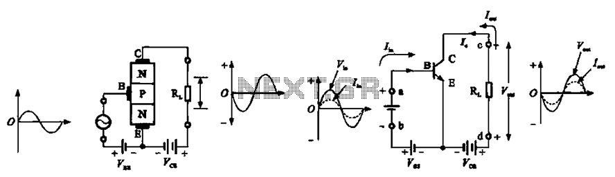
The common emitter amplifier is a fundamental building block in analog electronics, providing significant voltage amplification. The circuit typically consists of a bipolar junction transistor (BJT) configured to amplify the input signal applied at its base terminal. The output is taken from the collector terminal, which is inverted in phase relative to the input signal. This phase inversion is a key characteristic of the common emitter configuration, making it suitable for applications where signal inversion is required.
In terms of operation, when a small AC signal is applied to the base of the transistor, it modulates the base current, which in turn controls the larger collector current. This results in an amplified output voltage across the collector-emitter junction. The gain of the amplifier is determined by the ratio of the collector resistor to the emitter resistor, along with the transistor's characteristics. The common emitter amplifier typically achieves a voltage gain greater than one, often in the range of 10 to 100 or higher, depending on the specific circuit design and component values.
However, the common emitter amplifier's high output impedance presents challenges when interfacing with low impedance loads, such as speakers. The amplifier's inability to drive these loads directly necessitates the use of additional circuitry, such as a buffer stage or a power amplifier, to match the impedance and ensure efficient power transfer.
In summary, the common emitter amplifier is an essential component in signal processing, offering high voltage gain and phase inversion, but it requires careful consideration of output impedance when interfacing with load devices. Common emitter amplifier input and output signals of the phase relationship Common emitter amplifier circuit phase relationship of the input and output signals, as shown in FIG . (2) common emitter amplifier circuit basic functions by a common emitter amplifier circuits common-emitter transistor amplifier is often used as a voltage amplifier, in a wide variety of electronic devices which use. Its most prominent feature is a high voltage gain. Since the output impedance is higher than your daughter, so this voltage amplifier with a load capacity ratio is low, it can not directly drive a low impedance speaker loads.
Related Circuits
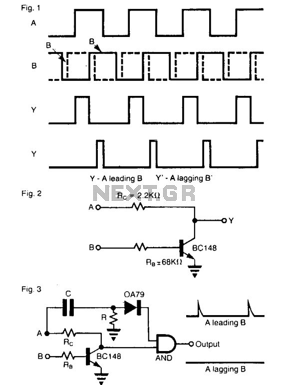
The operation of the circuit resembles that of an enabled inverter, where the output Y equals B when input A is high. If A is low, the output remains low, regardless of the state of B. When the signals...
The XLR or Cannon-type connector is a superior audio connector compared to a 6.5mm jack plug and socket. However, tradition mandates the use of the 6.5mm socket, despite its significant connection issues. Inputs can vary from a single socket...
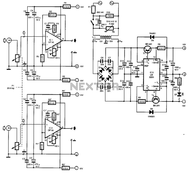
Built around Precision Monolithics Inc. OP-50 operational amplifiers, this amplifier is capable of driving 100- to 14-ohm headphones. It maintains a flat frequency response within 0.4 dB from 10 Hz to 20 kHz and exhibits a total harmonic distortion...
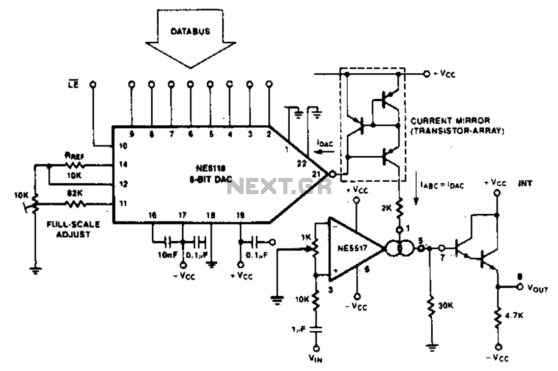
The purpose of the following application is to demonstrate how the NE5517 operates in conjunction with a DAC. The application utilizes the NE5118, an 8-bit DAC with current output, featuring an input register that makes this device fully micro-compatible....
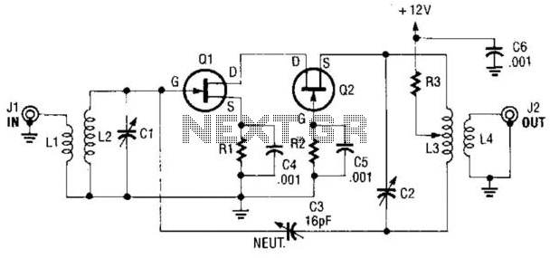
A cascode amplifier using two MOSFETs is illustrated in the diagram. L2C1 and L3C2 resonate at the operating frequency. The circuit offers advantages such as high gain, low noise figure (NF), and excellent linearity. Q1 and Q2 can be...
This is a nice amplifier and very easy to make it. Its an 20W Audio Amplifier based on LM1875 IC. More: Power supply - 48 VDC Output - 20 W, 4 ? Very low distortion (THD - 0.015%), good...
Warning: include(partials/cookie-banner.php): Failed to open stream: Permission denied in /var/www/html/nextgr/view-circuit.php on line 713
Warning: include(): Failed opening 'partials/cookie-banner.php' for inclusion (include_path='.:/usr/share/php') in /var/www/html/nextgr/view-circuit.php on line 713