
Composed of HS101/HS201 4 channels remote control switch circuit diagram
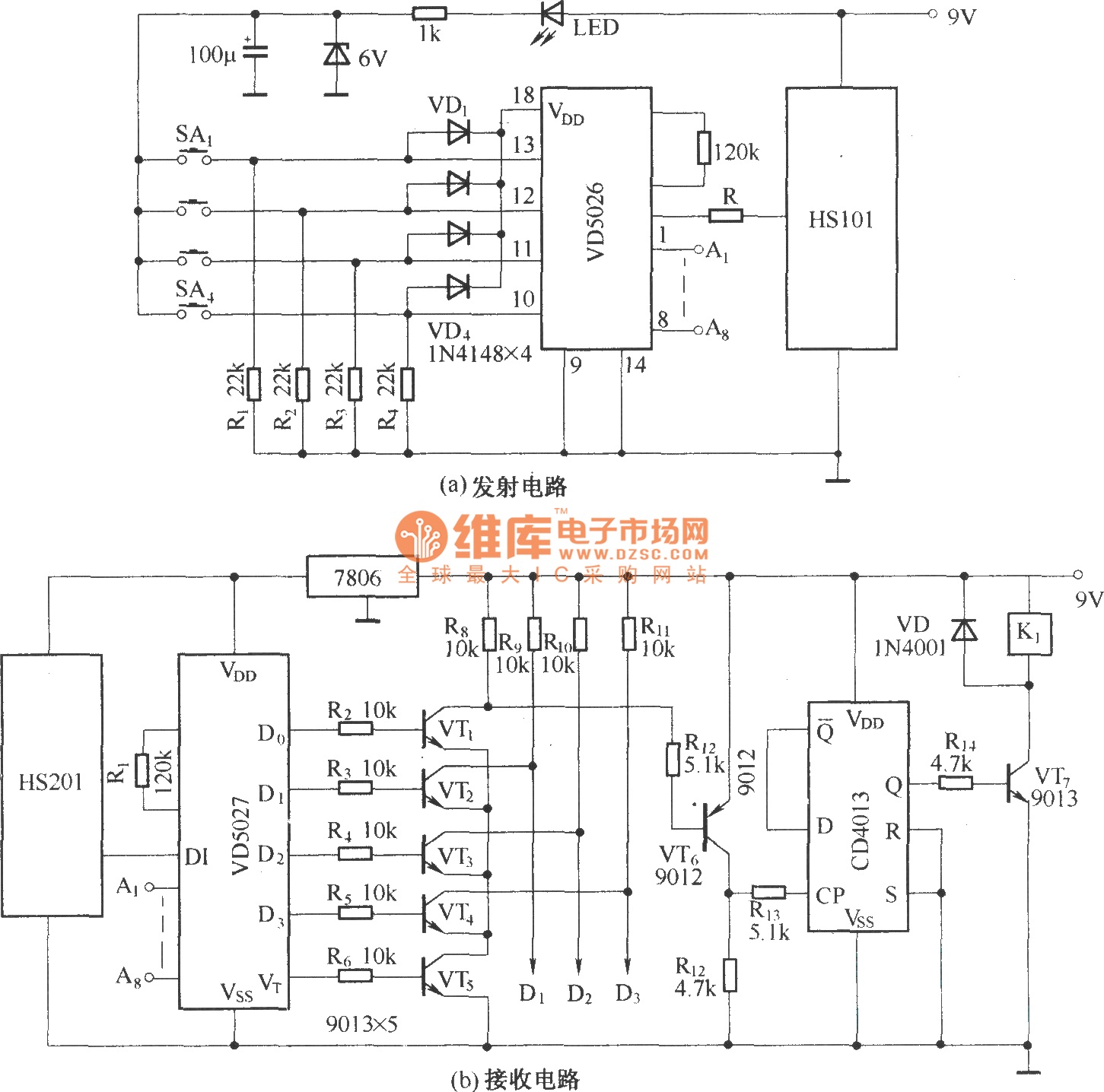
The HS101 and HS201 transceivers are compact devices that enable wireless communication for various applications, particularly in remote control systems. Operating at a frequency of 280 MHz, these transceivers are well-suited for environments where reliable digital signal transmission is required. The effective control range of 30 to 100 meters makes them ideal for applications such as remote switching, telemetry, and simple data communication.
The integration of all necessary components, including the antenna, into a single package simplifies the design and implementation process for engineers and hobbyists alike. This all-in-one design reduces the need for additional components, minimizing the overall footprint of the circuit and enhancing reliability by reducing the potential points of failure.
In the context of a four-channel remote control switch circuit, the HS101 and HS201 can be configured to control multiple devices or functions wirelessly. Each channel can be assigned to a different device, allowing for versatile control options. The circuit typically involves a microcontroller that processes the input signals from a remote control and communicates with the HS101/HS201 transceivers to send the appropriate commands.
The schematic for the four-channel remote control switch circuit would generally include the following components:
1. **Microcontroller**: This is the central processing unit that interprets user input and generates control signals.
2. **HS101/HS201 Transceiver Module**: This module handles the transmission and reception of radio signals.
3. **Power Supply**: A suitable power source is required to power the microcontroller and the transceiver.
4. **Antenna**: Integrated within the HS101/HS201 module, the antenna facilitates wireless communication.
5. **Switches**: These are used for user input to select the desired channel for control.
6. **Output Relays**: These are used to switch the controlled devices on or off based on the received signals.
Overall, the HS101 and HS201 transceivers provide a robust solution for wireless communication needs, enabling the development of efficient and effective remote control systems. Their compact design and ease of integration make them a favorable choice for both commercial and DIY electronics projects.HS101/HS201 are a pair of tiny radio transceiver components. The working frequency is 280MHz. It is suitable for digital signal transmission. The control distance is 30 ~ 100m. All the components including the antenna are packaged in one. It is easy to use. The four-channel remote control switch circuit composed of HS101/HS201 is shown as above. 🔗 External reference
Related Circuits
The objective is to identify a function generator or a voltage-controlled oscillator (VCO) suitable for generating two sine wave sound signals. One waveform should be fixed at a frequency, such as 440 Hz, while the second waveform must be...
A 1200 Watt lamp dimmer circuit is designed to control lighting levels and is capable of managing up to 1200 Watts. This circuit utilizes the Q4015LT, which combines a Diac and a Triac for 230V dimming applications. It serves...
Here is an amplifier circuit based on the BUZ11, which can be replaced by an IRFZ34N, and an ECC83 can be used instead of the ECC88. In this case, the anode voltage should be reduced slightly to 155 V....
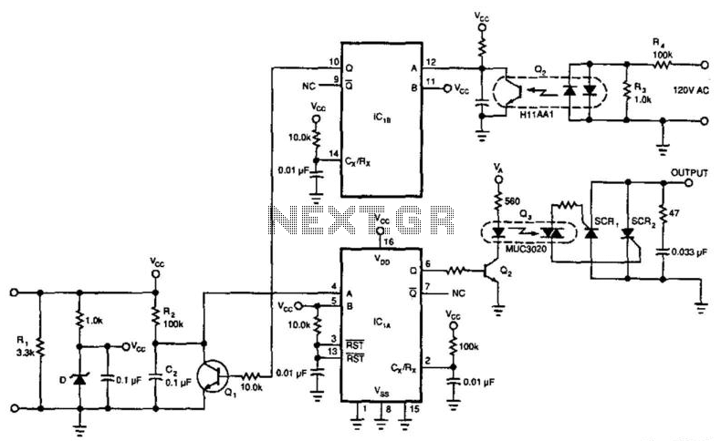
This circuit enables a 4-to-20 mA current loop to control an isolated SCR drive. IC1A and IC1B function as one-shot timers. Q2 detects zero crossings of the 120 Vac line, which triggers one-shot IC1B. IC1A causes Q1 to discharge...
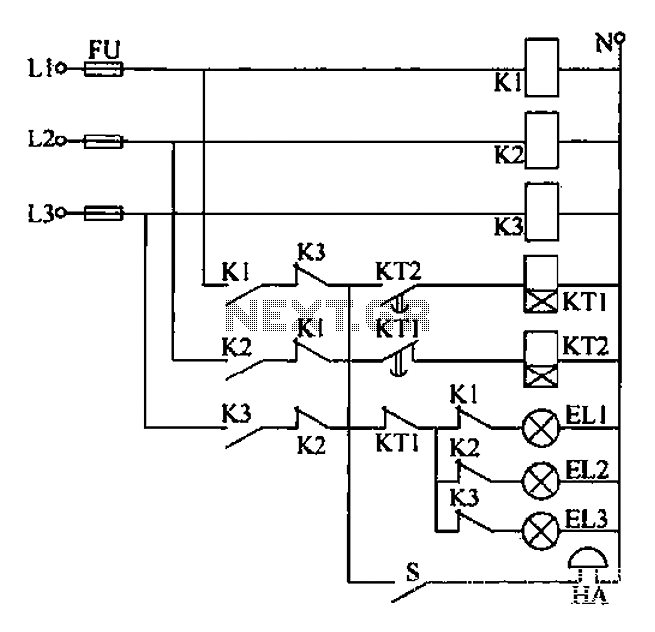
Any power supply and distribution sector should include phase sequence detection to ensure that the power supply phase sequence remains stable and unchanged. Additionally, any irreversible electromechanical product should also incorporate phase sequence detection to verify the phase sequence...
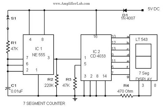
The circuit diagram of a 7-segment counter circuit has been published here. This circuit consists of the counter IC CD4033 as its central component. The 7-segment counter circuit utilizing the CD4033 integrated circuit (IC) is designed to display decimal digits...
Warning: include(partials/cookie-banner.php): Failed to open stream: Permission denied in /var/www/html/nextgr/view-circuit.php on line 713
Warning: include(): Failed opening 'partials/cookie-banner.php' for inclusion (include_path='.:/usr/share/php') in /var/www/html/nextgr/view-circuit.php on line 713