
Compressor-Limiter-Clipper for FM transmitters
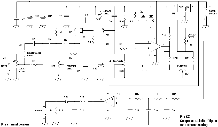
Characteristics:
Absolutely no signal overshooting (tested with PIRA75 FM Broadcast Analyzer)
Low noise and distortion
Simple to adjust
Only a few parts to solder
Precise preemphasis including HF clipping with no distortion audible
Stereo version available here
Supply voltage: 9-16 V
Quiescent supply current (12 V): 15 mA
Output voltage: linear adjustable 0-3.5 V p-p (0-1.2 V rms)
Lower cut-off frequency (3 dB): input: 25 Hz, output: <2 Hz
Upper cut-off frequency (3 dB): 14.5 kHz
Min. input voltage: 0.6 V p-p (0.2 V rms)
Input impedance: 5000 ohm
Output impedance: 500 ohm
Signal-to-noise ratio: >70 dB
Part list:
R1, R3 - 10k
R2 - 1k
R4, R5 - 1M
R6 - 18k
R7, R8, R15-R17, R19 - 33k
R9 - 1M5
R10, R12, R14, R18 - 470R
R11 - 270R
R20, R23, R25 - trimmer 5k
R21 - trimmer 5M
R22 - trimmer 1k
R24 - trimmer 500R
C1 - 4n7 (EU) or 6n8 (USA), plastic
C2 - 470n plastic
C3 - 4n7 plastic
C4 - 330n plastic
C5, C7, C8, C12 - 10n ceramic
C6 - 22n ceramic
C9 - 330p ceramic
C10 - 470p ceramic
C11 - 82p ceramic
C13 - 10u/25V tantalum
C14 - 470u/25V electrolytic
C15, C16 - 220u/10V electrolytic
U1 - TLC272
U2 - 78L05
Q1 - BC557B
Q2 - BF245C
D1, D2 - Red LED diode 5 mm, medium luminance (e.g., 200 mcd)
J2 - jumper
The described circuit functions as an audio limiter designed to manage the dynamic range of audio signals effectively. It addresses the challenges posed by varying signal levels in music or speech, ensuring that the output remains within a constant level suitable for transmission. The limiter operates by attenuating excessively loud signals while amplifying quieter sections, thus producing a balanced output.
The circuit is powered by a supply voltage ranging from 9 to 16 volts, with a quiescent current draw of 15 mA at 12 volts. This low power consumption makes it suitable for portable applications. The output voltage can be adjusted linearly from 0 to 3.5 V peak-to-peak, which corresponds to an effective RMS voltage of up to 1.2 V. The input and output stages are designed to handle a range of frequencies, with a lower cut-off frequency of 25 Hz and an upper cut-off frequency of 14.5 kHz, ensuring that the audio quality is maintained across the audible spectrum.
The input impedance of 5000 ohms and output impedance of 500 ohms are optimized for compatibility with various audio sources and loads. A signal-to-noise ratio exceeding 70 dB indicates the circuit's ability to minimize noise, contributing to high fidelity audio transmission.
The component list details the necessary resistors, capacitors, and integrated circuits required for assembly. Notably, the use of a TLC272 operational amplifier (U1) ensures low noise and distortion characteristics, while the BF245C transistor (Q2) aids in signal processing. The inclusion of trimmer potentiometers allows for fine-tuning of the circuit parameters, enhancing adjustability.
This limiter circuit is a practical solution for any audio transmission system lacking built-in dynamic range control, providing a simple yet effective means to achieve high-quality audio output without unnecessary complexity or features.Audio signals as music or speech have big dynamic ranges. There are silent and loud sections. These audio signals aren't too good for a transmitter, which requires audio signal with constant level on the input. Limiter is a device, which weakens loud signals and intensifies silent signals. On its output there is signal with constant level. Signal clipping on the limiter output allows to increase the signal level without exceeding maximum frequency deviation limit 75 kHz.
It's very suitable since preemphasis is used. If your transmission chain does not include any similar device, you should build this one. You will be surprised by its quality, efficiency and simplicity. Be careful if you want to buy any simple compressor/limiter board available on the market! Although a big list of features is mentioned, some of these toys have no signal overshooting protection and have no precise preemphasis with HF clipping option. With these devices it's not possible to keep loud sound AND meet the frequency deviation limit. So there is no reason why to pay for them. The device should guarantee basic technical characteristics of the modulation signal, nothing more - no equalizers and other disutilities.
Characteristics: Absolutelly no signal overshooting (tested with PIRA75 FM Broadcast Analyzer) Low noise and distortion Simple to adjust Only a few parts to solder Precise preemphasis including HF clipping with no distortion audible Stereo version available here Supply voltage: 9-16 V Quiescent supply current (12 V): 15 mA Output voltage: linear adjustable 0-3.5 V p-p (0-1.2 V rms) Lower cut-off frequency (3 dB): input: 25 Hz, output: <2 Hz Upper cut-off frequency (3 dB): 14.5 kHz Min. input voltage: 0.6 V p-p (0.2 V rms) Input impedance: 5000 ohm Output impedance: 500 ohm Signal-to-noise ratio: >70 dB Part list: R1, R3 - 10k R2 - 1k R4, R5 - 1M R6 - 18k R7, R8, R15-R17, R19 - 33k R9 - 1M5 R10, R12, R14, R18 - 470R R11 - 270R R20, R23, R25 - trimmer 5k R21 - trimmer 5M R22 - trimmer 1k R24 - trimmer 500R C1 - 4n7 (EU) or 6n8 (USA), plastic C2 - 470n plastic C3 - 4n7 plastic C4 - 330n plastic C5, C7, C8, C12 - 10n ceramic C6 - 22n ceramic C9 - 330p ceramic C10 - 470p ceramic C11 - 82p ceramic C13 - 10u/25V tantalum C14 - 470u/25V electrolytic C15, C16 - 220u/10V electrolytic U1 - TLC272 U2 - 78L05 Q1 - BC557B Q2 - BF245C D1, D2 - Red!!!
LED diode 5 mm, medium luminance (eg. 200 mcd) J2 - jumper 🔗 External reference
Related Circuits
Antenna is the means by which a wireless operator puts his signal into the space and also through which he picks up the signals of the stations with which he wants to communicate. Hence after having a good Receiver...
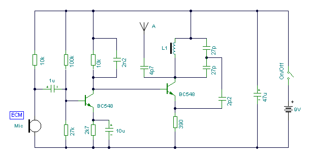
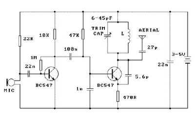
This circuit can be adjusted to operate within the frequency range of 87-108 MHz, achieving a transmission distance of approximately 20 to 30 meters. The design incorporates a pair of BC548 transistors, which, while not specifically designated as RF...
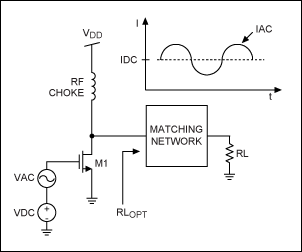
This application note provides a concise overview of power amplifier theory and presents simulation results that offer insights into the operation of the power amplifier across all of MAXIM's LFRF transmitters and transceivers. Power amplifiers are critical components in communication...
Place the transmitter approximately 10 feet away from an FM radio. Set the radio to a frequency between 89 and 90 MHz. Walk back to the FM transmitter and turn it on. Separate the windings of the coil by...
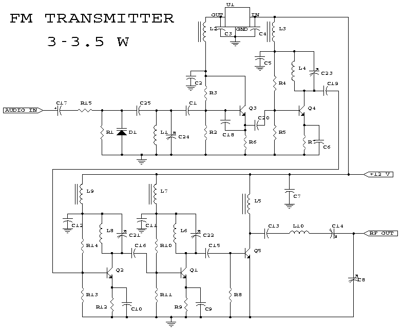
This schematic represents an FM transmitter capable of delivering an output power ranging from 3 to 3.5 watts, operational within the frequency band of 90 to 110 MHz. While the circuit exhibits reasonable stability, a Phase-Locked Loop (PLL) can...
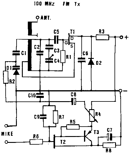
Information about building a small radio transmitter, which has a PCB measuring 1.75" x 2.5" (45mm x 68mm) and has a range of approximately 30 yards. The documentation states that the frequency range is 100-108 MHz, but it has...