
computer-circuits
This simple PC scope probe functions as a FET follower, featuring high input impedance and low output impedance to match a microphone or line input socket on a PC or laptop. This design allows for practical examination of waveforms under test, such as logic square waves with a peak-to-peak voltage of 5V, without loading the circuit source point. The output will remain within a safe millivolt range acceptable for sensitive sound card inputs. Installed oscilloscope or spectrum analyzer software will display essential elements of the desired waveform. Note that sine waves and square waves with a 50:50 duty cycle up to 20 kHz can be analyzed effectively. However, examination of fast rate clock signals and transient pulses is limited due to the sound card's poor rise time response, not the probe's limitations. The probe accurately transfers the signals it receives. Two 47 µF capacitors allow for the passage of low frequencies; the first capacitor blocks DC from the FET source pin, while the second capacitor blocks the +3V DC phantom power output from the PC microphone socket. For a simple open-plan construction, the nine components can fit on a piece of veroboard measuring 43 mm by 16 mm. After soldering, component legs should be trimmed. Maplin board pins with code FL24 can be utilized for all external wiring connections. To secure the board to the plastic, cut double-sided sticky tape to size, apply it, and press the surfaces together firmly. The red and black battery wires should be soldered correctly to the board.
This PC scope probe circuit is designed to serve as an effective interface for observing electrical waveforms using a personal computer's sound card. The FET follower configuration ensures that the probe does not load the circuit under test, which is critical for accurate waveform analysis. The high input impedance minimizes the effect on the circuit being measured, allowing for true representation of the signal.
The use of two 47 µF capacitors is integral to the function of the probe. The first capacitor serves to block any DC voltage that may interfere with the AC signal being measured, while the second capacitor prevents any unintended DC bias from the microphone input of the PC. This design consideration is essential for maintaining signal integrity and ensuring that only the desired AC waveform is passed to the sound card.
The veroboard layout is compact, allowing for a straightforward assembly process. By cutting the board to the specified dimensions, all components can be arranged efficiently, ensuring minimal signal path length and reducing potential interference. The use of Maplin board pins for external connections simplifies the integration of the probe into various setups, enhancing versatility.
To achieve a reliable and robust construction, the use of double-sided sticky tape for securing the board is recommended. This method not only provides a clean aesthetic but also ensures that the components are held firmly in place, preventing any movement that could lead to signal degradation.
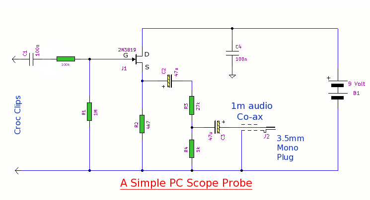
Overall, this simple PC scope probe is a valuable tool for hobbyists and professionals alike, enabling effective waveform analysis while maintaining the integrity of the signals being measured. It is important to follow the assembly instructions carefully to ensure optimal performance and reliability.This simple pc scope probe is nothing more than a fet follower. It has a high input impedance and a low output impedance tomatch a mic or line input socket on a pc or laptop. This means it is then practical to examine waveforms under test, for example logic square waves of 5v peak-to-peak, withoutloading the circuit source point.
The resulting term inated output will thus be within a safe mVrange as can be accepted by the sensitive sound card input. Installed oscilloscope/spectrum analyser software willdisplay essential elements of the wanted waveform.
Proviso: Sine waves and square waves of 50:50 duty cycle to 20khz are no problem to check. But examination of fast rate clock and transient pulses is not possible due to the sound card`s poor risetime response and not by limitations of the probe itself. The probe will faithfully transfer exactly what it receives. Both 47mfd capacitors pass down to low frequencies. The first 47mfd cap blocks dc from the fet source pin and the second 47mfdcap blocks the phantom +3v dc outputted from the pc mic socket.
If a simple open-plan construction will suffice, the nine componentswill fit on a piece of veroboard cut to 43mm by 16mm. Close-crop the component legs after soldering. Maplin board pins of code FL24, can be used for all external wiringconnections. To secure the board trackside to the plastic, cut to size double-sided sticky tape, apply then press the two surfaces carefully and firmly together.
Solder the red and black battery wires correctly to the board. 🔗 External reference
This PC scope probe circuit is designed to serve as an effective interface for observing electrical waveforms using a personal computer's sound card. The FET follower configuration ensures that the probe does not load the circuit under test, which is critical for accurate waveform analysis. The high input impedance minimizes the effect on the circuit being measured, allowing for true representation of the signal.
The use of two 47 µF capacitors is integral to the function of the probe. The first capacitor serves to block any DC voltage that may interfere with the AC signal being measured, while the second capacitor prevents any unintended DC bias from the microphone input of the PC. This design consideration is essential for maintaining signal integrity and ensuring that only the desired AC waveform is passed to the sound card.
The veroboard layout is compact, allowing for a straightforward assembly process. By cutting the board to the specified dimensions, all components can be arranged efficiently, ensuring minimal signal path length and reducing potential interference. The use of Maplin board pins for external connections simplifies the integration of the probe into various setups, enhancing versatility.
To achieve a reliable and robust construction, the use of double-sided sticky tape for securing the board is recommended. This method not only provides a clean aesthetic but also ensures that the components are held firmly in place, preventing any movement that could lead to signal degradation.
Overall, this simple PC scope probe is a valuable tool for hobbyists and professionals alike, enabling effective waveform analysis while maintaining the integrity of the signals being measured. It is important to follow the assembly instructions carefully to ensure optimal performance and reliability.This simple pc scope probe is nothing more than a fet follower. It has a high input impedance and a low output impedance tomatch a mic or line input socket on a pc or laptop. This means it is then practical to examine waveforms under test, for example logic square waves of 5v peak-to-peak, withoutloading the circuit source point.
The resulting term inated output will thus be within a safe mVrange as can be accepted by the sensitive sound card input. Installed oscilloscope/spectrum analyser software willdisplay essential elements of the wanted waveform.
Proviso: Sine waves and square waves of 50:50 duty cycle to 20khz are no problem to check. But examination of fast rate clock and transient pulses is not possible due to the sound card`s poor risetime response and not by limitations of the probe itself. The probe will faithfully transfer exactly what it receives. Both 47mfd capacitors pass down to low frequencies. The first 47mfd cap blocks dc from the fet source pin and the second 47mfdcap blocks the phantom +3v dc outputted from the pc mic socket.
If a simple open-plan construction will suffice, the nine componentswill fit on a piece of veroboard cut to 43mm by 16mm. Close-crop the component legs after soldering. Maplin board pins of code FL24, can be used for all external wiringconnections. To secure the board trackside to the plastic, cut to size double-sided sticky tape, apply then press the two surfaces carefully and firmly together.
Solder the red and black battery wires correctly to the board. 🔗 External reference
Warning: include(partials/cookie-banner.php): Failed to open stream: Permission denied in /var/www/html/nextgr/view-circuit.php on line 713
Warning: include(): Failed opening 'partials/cookie-banner.php' for inclusion (include_path='.:/usr/share/php') in /var/www/html/nextgr/view-circuit.php on line 713