
Computer Microphone
The circuit employs a two-stage amplifier design to effectively adapt a common electret microphone for use with a PC sound card. The first stage utilizes the BC413B transistor configured in a common emitter arrangement. This configuration is advantageous for providing voltage gain, which enhances the low-level audio signal from the electret microphone. The gain achieved in this stage is crucial for compensating for the inherent low output of electret microphones, which typically require additional amplification to achieve adequate signal levels for processing by the sound card.
Following the initial amplification stage, the signal is fed into the second stage, which employs the BC547C transistor configured as an emitter follower. The emitter follower configuration is characterized by its high input impedance and low output impedance, making it ideal for driving longer cable runs without significant signal degradation. This is particularly important in applications where the microphone and associated circuitry are situated at a distance from the sound card, as it minimizes the risk of noise pickup and signal loss.
The overall design ensures that the output signal remains strong and clear, allowing for effective audio capture and transmission to the sound card. The use of screened cables further enhances the circuit's performance by shielding against electromagnetic interference, which can be a significant issue in audio applications. This setup is particularly beneficial for users who wish to utilize electret microphones in environments where traditional dynamic microphones may not be suitable or available.This circuit was submitted by Lazar Pancic from Yugoslavia. The sound card for a PC generally has a microphone input, speaker output and sometimes line inputs and outputs. The mic input is designed for dynamic microphones only in impedance range of 200 to 600 ohms. Lazar has adapted the sound card to use a common electret microphone using this cir cuit. He has made a composite amplifier using two transistors. The BC413B operates in common emitter to give a slight boost to the mic signal. This is followed by an emitter follower stage using the BC547C. This is necessary as the mic and circuit and battery will be some distance from the sound card, the low output impedance of the circuit and screened cable ensuring a clean signal with minimum noise pickup. 🔗 External reference
Related Circuits
This document provides information on the technical aspects of monitoring meteor counts through VHF radio receivers. It aims to address gaps in existing literature and offers alternative perspectives on observational techniques, supported by real data. While many online resources...
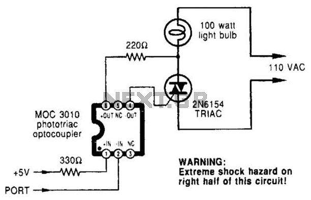
A microcomputer-to-triac interface utilizes a phototriac optoisolator to safely isolate logic signals, allowing direct control of high-power loads. This circuit can function as either an on/off switch or a proportional phase control, depending on the input waveforms and the...
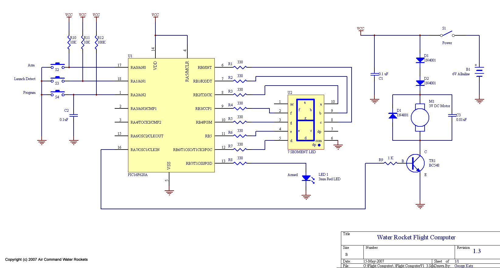
The design modifications were primarily selected to enhance the system's weight efficiency. The majority of weight reduction was achieved through the implementation of a single board design, transitioning to single battery operation, and directly mounting the battery onto the...
The circuit monitors PC keyboard activity through a five-pin DIN connector J1. When a key is pressed, the keyboard transmits a series of negative-going pulses on pin 2. In conjunction with Q1 and C3, the operational amplifier operates as...
Dynamic microphones are versatile and ideal for general-purpose use. They utilize a straightforward design with minimal moving parts, making them relatively sturdy and resilient to rough handling. These microphones are better suited for high volume levels, such as those...
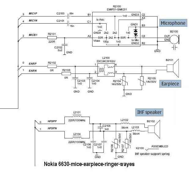
The microphone issue on the Nokia 6630 is typically attributed to several factors, including a damaged microphone, a broken circuit path, or a faulty UEM IC. If the issue arises from a broken path in the microphone circuit, it...
Warning: include(partials/cookie-banner.php): Failed to open stream: Permission denied in /var/www/html/nextgr/view-circuit.php on line 713
Warning: include(): Failed opening 'partials/cookie-banner.php' for inclusion (include_path='.:/usr/share/php') in /var/www/html/nextgr/view-circuit.php on line 713