
Connection of the stator coils b
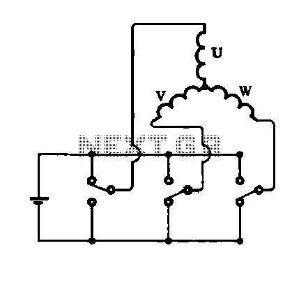
The stator coils in an electric machine are crucial components that generate the magnetic field necessary for operation. The triangular (delta) and star (wye) configurations are two common methods for connecting these coils.
In a triangular connection, each coil is connected end-to-end, forming a closed loop that allows for higher voltages and is typically used in applications requiring higher starting torque. This configuration can be advantageous in scenarios where the power supply can handle the increased voltage, as it allows for a more robust current flow through the coils.
Conversely, the star connection involves connecting one terminal of each coil to a common point, while the other terminals are connected to the power supply. This configuration is often preferred for its ability to reduce the starting current and provide a smoother operation, making it suitable for applications where a gradual increase in torque is desired.
In practical applications, the choice between triangular and star connections depends on various factors, including the specific requirements of the motor, the nature of the load, and the characteristics of the power supply. Understanding these configurations allows engineers to optimize the performance and efficiency of electric machines in various industrial and commercial applications.Connection of the stator coils b Shows the structure and connections of the stator coil, and FIG. (A) shows a triangular connection, Figure (b) shows a star connection, star co nnection in two forms.
Related Circuits
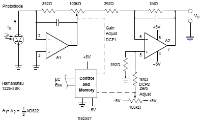
Photovoltaic (PV) technology involves the application of solar cells to convert sunlight directly into electricity. The provided manual on Photovoltaic Power Systems outlines practices in accordance with the 2005 National Electrical Code (NEC) relevant to PV power systems. This...
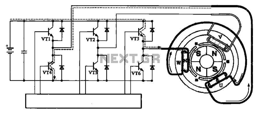
The brushless motor consists of a rotor, a stator, and a drive circuit. The relationship between the brushless motor rotor, stator, and drive circuit is illustrated in the accompanying figure. In the initial state, VT3 and VT4 are conducting,...
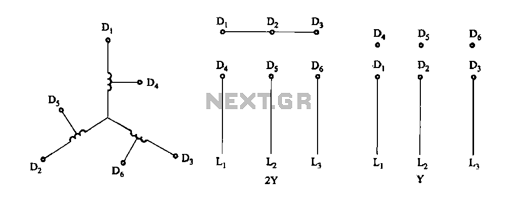
Figure 3-100 illustrates the lead wiring diagram for the stator windings of a two-speed motor configured in a 2Y/Y connection. The two-speed motor stator wiring diagram depicted in Figure 3-100 provides a clear representation of the electrical connections required for...
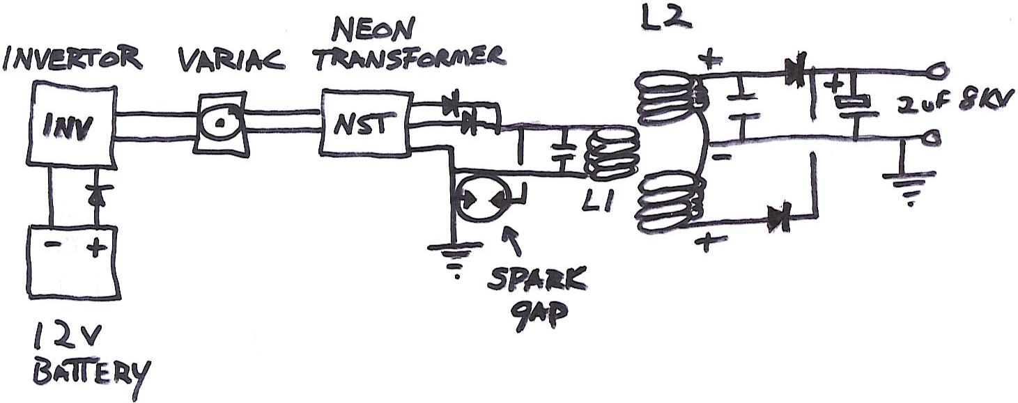
This diagram illustrates all components necessary to create a self-sustaining power supply. The input is a 12V DC, 7Ah lead-acid or gel cell battery (not depicted). This input connects to a 12V DC to 120V AC inverter rated approximately...
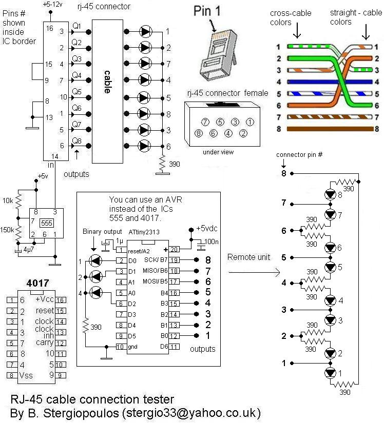
Here is a very simple yet practical circuit designed to check the type of LAN cables (straight or cross) as well as to identify possible faults. The circuit utilizes a unit with 8 outputs, each producing a pulse successively,...
Due to the high voltages present in the Charge and Primary sections, it is logical to seek cables with high voltage ratings, such as neon sign cables, medical X-ray equipment cables, and car engine spark plug leads. The first...
Warning: include(partials/cookie-banner.php): Failed to open stream: Permission denied in /var/www/html/nextgr/view-circuit.php on line 713
Warning: include(): Failed opening 'partials/cookie-banner.php' for inclusion (include_path='.:/usr/share/php') in /var/www/html/nextgr/view-circuit.php on line 713