
Constant current LED driver using LM3410
The LM3410 LED driver circuit is designed to provide efficient power management for LED applications, capitalizing on the integrated features of the LM3410 to minimize component count and enhance reliability. The device's current-mode control mechanism allows for precise regulation of the LED current, ensuring consistent brightness across varying input voltages. This is particularly beneficial in battery-operated devices where voltage fluctuations can occur.
The thermal shutdown feature is crucial for protecting the circuit from overheating, which can lead to LED failure or damage to the driver itself. By monitoring the internal temperature, the LM3410 can disable the output when it exceeds a predetermined threshold, allowing for safe operation in high-temperature environments.
The PWM dimming capability allows for versatile control of the LED brightness, making it suitable for applications requiring variable intensity lighting. By connecting a PWM signal to the DIM terminal, users can easily adjust the average LED current, thereby controlling the perceived brightness without introducing flicker.
In terms of component selection, the use of small surface mount inductors and capacitors is facilitated by the high switching frequency of 1.6MHz, which reduces the size of the passive components needed in the circuit. This results in a compact design that is ideal for space-constrained applications.
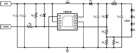
Overall, the LM3410 constant current LED driver circuit is an effective solution for driving multiple LEDs in series, offering a combination of efficiency, reliability, and ease of use, making it suitable for a wide range of lighting applications.Using the LM3410 constant current LED driver is a monolithic IC we can design, many high efficiency and low cost lights, using just few electronic components. The LM3410 utilizes current-mode control and internal compensation to provide high-performance over a wide range of operating conditions.
Additional features include dimming, cycle-by-cyc le current limit, and thermal shutdown. This LED driver schematic circuit is designed to drive four, on-board LEDs (VOUT = 11. 4V) in series at an average LED current (ILED) of 190mA. The circuit can accept an input voltage of 3. 3V-5. 5V. The switching frequency of the LM3410 converter is 1. 6MHz allowing the use of small surface mount inductors and chip capacitors. This LED driver circuit also features the PWM capability of the LM3410 by enabling the user to apply a periodic pulse signal to the DIM terminal of varying duty cycle. 🔗 External reference
Related Circuits
The current loop interface circuit diagram of the AD694 multi-functional sensor signal conditioner is utilized as a digital-to-analog converter (DAC). This current loop interface enables the conversion of digital values into voltage and subsequently into current signals. The circuit...
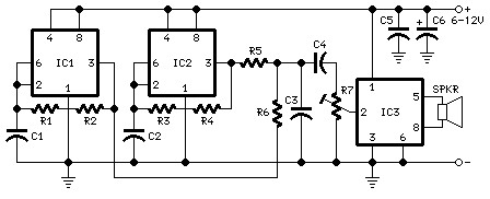
The following diagram is the schematic diagram for a car horn circuit, which can be utilized for car modifications. Components List: R1 = 68K, R2 = 2K2, R3 = 56K, R4 = 3K3, R5, R6 = 4K7, R7 =...
By utilizing a high-gain, high-impedance operational amplifier, it is possible to construct a long time delay circuit using a resistor-capacitor (RC) configuration, as it allows for high... An operational amplifier (op-amp) is a versatile component widely used in electronic circuits,...
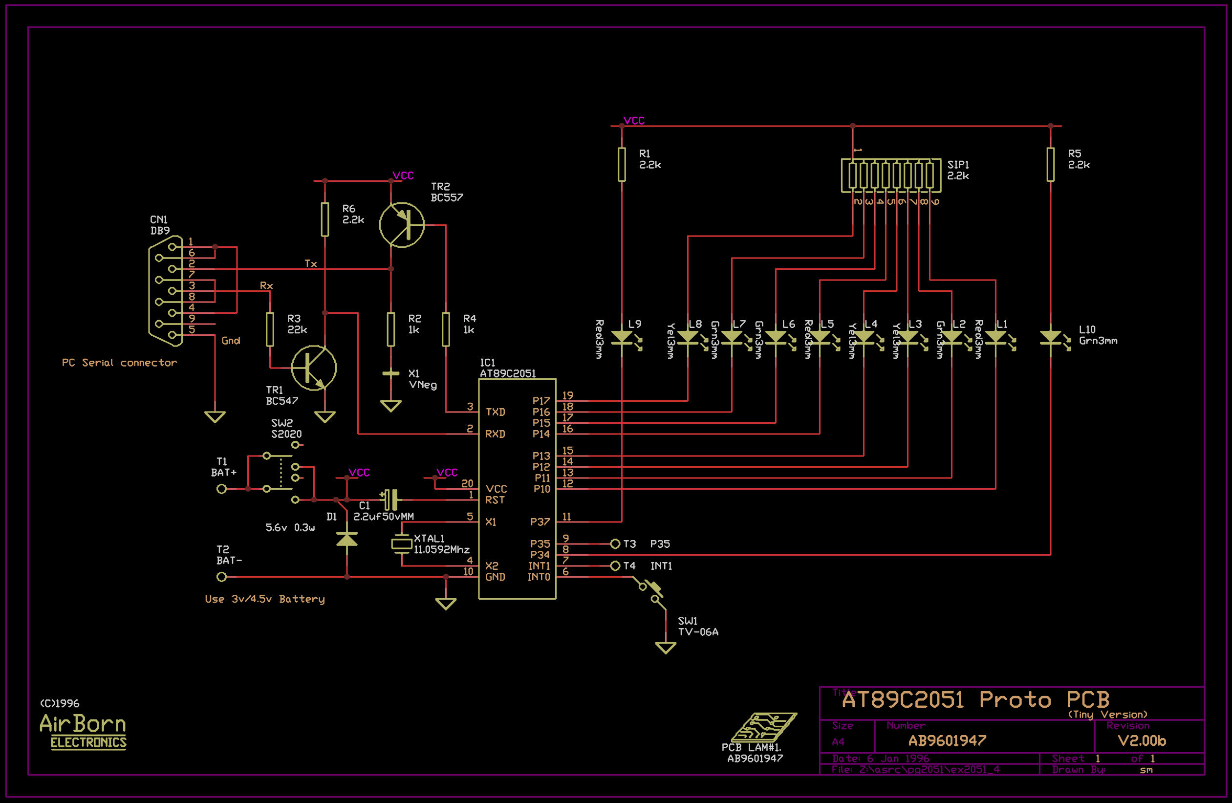
The example program included with the PG2051 evaluation kit is a basic serial to parallel converter written in 8051 assembler. This is probably a good example of the uses to which an AT89C2051 can be put - it would...
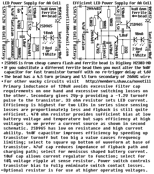
Efficiency can be increased by using a germanium transistor at the 33 ohm current sense resistor, and by using a proper torroid core in place of the crappy ferrite bead. Single AA cell powers two LEDs at constant current. The...
In the circuit below, 60 individual LEDs are used to indicate the minutes of a clock and 12 LEDs indicate hours. The power supply and time base circuitry is the same as described in the 28 LED clock circuit...