
Constant Current LED Tester
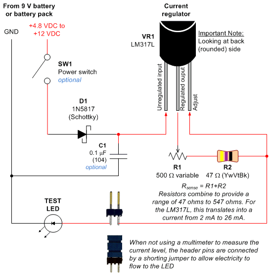
SW1 serves as an optional power switch since current only flows through the test LED and capacitor (C1). Low-value ceramic capacitors exhibit minimal leakage current, making the power switch unnecessary when idle. C1, while optional, is typically used for stability in regulators and ICs, although its necessity in this circuit is minimal due to the absence of critical conditions. The test LED, or any load, draws power through resistors R1 and R2. The adjust pin of the LM317L measures the voltage drop across R1 and R2, allowing it to determine the current flowing through both components. According to Ohm's law, the current through a fixed resistor results in a corresponding voltage drop, enabling the LM317L to regulate the current delivered to the LED by continuously measuring this voltage drop and adjusting the output voltage accordingly.
R1 is a potentiometer that can vary its resistance from 0 ohms to 500 ohms, allowing for current adjustment. R2 is a fixed resistor that limits the maximum current to 26 mA as specified in the LM317L datasheet. Without R2, setting the potentiometer to 0 ohms could result in excessive current (up to 300 mA) flowing to the LED, risking damage. Therefore, R2 serves a protective role for the LED.
The circuit's operation is based on a feedback mechanism that ensures the current remains within safe limits while allowing for easy adjustments. By implementing a sense resistor configuration with R1 and R2, the circuit effectively monitors and regulates the current supplied to the LED, enhancing its reliability and performance in practical applications.Most of my circuits still use 5 V regulated power for the chips, because 8-bit microcontrollers run faster and some sensors require 5 V. Since 5 V is more than enough for even a white LED, I`m not concerned with the voltage needed by a particular LED in use.
However, since my robots are battery powered, I am concerned with the current usage, since that determines how quickly the battery is exhausted. Furthermore, an LED can be destroyed by too much current (usually anything beyond 30 mA). Therefore, I decided to make the LED tester based on current, not voltage. As described previously, the LED tester can be set to supply a specific current from 2 mA to 26 mA. The circuit will automatically vary the voltage from nearly 0 V to about 7. 5 volts in order to supply the current. I don`t need to adjust the voltage, and I don`t need to care about the current after I`ve set it. Many people are accustomed to voltage regulators, like the standard 7805. But, surprisingly, most voltage regulators can be set up to regulate current instead. For this circuit, I chose the National Semiconductor LM317L that I purchased from DigiKey or Mouser Electronics (or LM317LZ from Electronic Goldmine ). The LM317L is cheap, small, and includes instructions in the datasheet for using it as a current regulator.
The semiconductor circuitry inside of the LM317L uses a simple feedback loop to automatically vary the output voltage to meet the required current. SW1: (optional) The power switch is optional in this circuit because current can only pass through a test LED and the capacitor (C1).
Low value ceramic capacitors at low voltages leak very little current (less than 1/10 of a nanoamp as far as I could measure). And, there`s no point of connecting a test LED with the power off. Since no power will be used when idle, the power switch is unnecessary. C1: (optional) Most regulators and integrated circuits achieve stability from the addition of capacitors.
There`s nothing critical going on in this circuit (no computations, high currents, current spikes, or high voltages). So, this capacitor is probably unnecessary. The test LED (or any other load) draws power from output pin through R1+R2. The adjust pin measures the voltage just after R1+R2. By subtracting the adjust voltage from the output voltage, the LM317L is able to measure exactly how much voltage is dropped across R1+R2.
Because all current that passes through the LED must first pass through R1+R2, the current must be the same for the LED and R1+R2. According to Ohm`s law, the current that passes through a fixed resistor results in a proportional voltage drop.
Therefore, the more current drawn by the LED, the more current passes through R1+R2, the greater the voltage drop across R1+R2. The less current drawn by the LED, the less current passes through R1+R2, the lower the voltage drop across R1+R2.
So, the LM317L is able to regulate the total current delivered to the LED by constantly measuring the voltage dropped across the sense resistor (R1+R2) and then lowering or raising the voltage at the output pin accordingly. By the way, a fixed resistor configured to measure current by measuring voltage drop is called a sense resistor.
For example, a small resistor (less than 1 ohm) is often placed in series with a motor driver circuit to detect how much current a motor is drawing. R1: The potentiometer can change resistance from 0 ohms to 500 ohms. As previously discussed, this alters the output voltage of the LM317L to allow you to adjust the current provided.
R2: This fixed resistor provides a maximum current limit of 26 mA based on the LM317L datasheet`s formula. If this resistor wasn`t included in the circuit and the potentiometer was dialed to 0 ohms, the test LED would receive significantly more current from the LM317L (perhaps as much as 300 mA), damaging the LED.
So, this resistor exists to protect the LED. You could actually use this 🔗 External reference
Related Circuits
This project involves creating an RGB LED-lit love heart controlled by a PIC12F683 microcontroller. The design serves as a gift for a 15th wedding anniversary. The heart is crafted from a 200x150x6mm sheet of plexiglass, which is cut and...

A simple LED voltmeter is designed to monitor the charge level in a lead-acid battery or tubular battery. The terminal voltage of the battery is displayed using four LED indicators. The nominal terminal voltage for a lead-acid battery is...
Common Light Emitting Diodes (LEDs) require a direct current (DC) forward bias of 10 to 20 mA for optimal performance. The maximum allowable DC current typically ranges from 30 to 50 mA. The emitted light color, or wavelength, from...
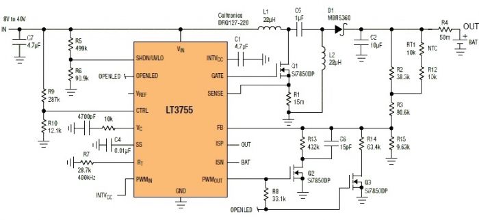
This Sealed Lead Acid Battery Charger is designed using the LT3755 DC-DC controller. The LT3755 is a DC-DC controller that operates as a constant-current source and supports a wide input voltage range from 4.5 to 40 volts, providing a...
This simple circuit can create an 18 LED flasher to decorate a Christmas tree. The white, blue, and red LEDs flash at different rates to provide a colorful display. It is a light-sensitive circuit, automatically activating in the evening...
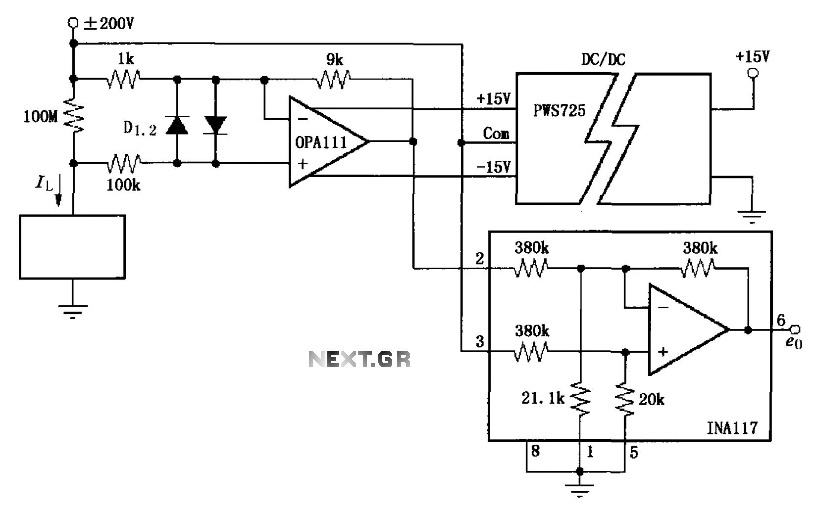
The circuit illustrated in FIG OPA111 is designed for measuring input buffer leakage current. The transistors D1 and D2, which are 2N3904 types, short the base and collector contacts while leaving the emitter open. When a power supply of...
Warning: include(partials/cookie-banner.php): Failed to open stream: Permission denied in /var/www/html/nextgr/view-circuit.php on line 713
Warning: include(): Failed opening 'partials/cookie-banner.php' for inclusion (include_path='.:/usr/share/php') in /var/www/html/nextgr/view-circuit.php on line 713