
Constant-current-stimulator
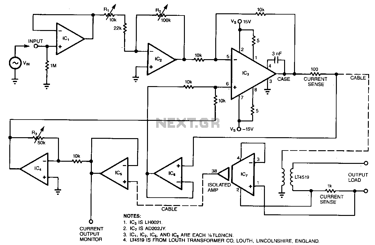
Most circuits that provide an electrical stimulus for research subjects are constant-voltage designs; this circuit is a constant-current design. Stimulator circuits must be isolated for two reasons: to ensure safety and to minimize interference. Isolated stimulators are essentially two-terminal devices; output currents can flow only between the two output terminals and cannot flow through any other path, such as the power ground. The circuit's bandwidth ranges from 50 Hz to 5 kHz when a ±1 V sinusoidal input drives the circuit. Output loads can range from a short circuit to 100 kΩ and can have as much as 0.033 μF of parallel capacitance. The transformer and associated circuitry conveniently connect to the main circuit via a cable. Note: This circuit is not approved for use on human beings. Operational amplifiers, IC1 and IC2, buffer and set the gain of the circuit, respectively. Trimmer R1 is adjusted so that R2, a 10-turn potentiometer, yields output currents ranging from 0 to 1 mA/Vin. IC3 is a power operational amplifier. Its output drives the primary of a transformer that has a current gain of 0.1, or a voltage gain of 10. Operating from a +15 V supply, the transformer therefore has a voltage compliance of ±150 V. The circuit senses not only the current supplied to the transformer but also the current in the transformer's secondary. IC7, a fully isolated, medical-grade amplifier, provides the isolated feedback signal because the operational amplifier has its own built-in isolation transformer. Trimmer R3 sets the feedback gain precisely at 27 kΩ nominal.
The described circuit is a constant-current stimulator designed for research applications, emphasizing safety and minimal interference through isolation. The design ensures that output currents are confined to the two output terminals, preventing any unintended paths that could compromise safety or performance.
The operational bandwidth of the circuit spans from 50 Hz to 5 kHz, making it suitable for various stimulation protocols. The input is driven by a ±1 V sinusoidal signal, which is an effective method for generating controlled electrical stimuli. The output can accommodate a wide range of loads, from short circuits up to 100 kΩ, while also managing a parallel capacitance of up to 0.033 μF. This flexibility in load handling is crucial for diverse experimental setups.
The circuit employs a transformer that interfaces with the main circuitry through a cable, facilitating easy integration into existing systems. It is important to note that this circuit is not approved for human use, highlighting the need for caution in its application.
Operational amplifiers IC1 and IC2 play vital roles in buffering and gain adjustment. The trimmer resistor R1 allows for fine-tuning the output, while R2, a 10-turn potentiometer, enables precise control over the output current, which can vary from 0 to 1 mA/Vin. This feature is essential for adapting the circuit to specific experimental requirements.
IC3 serves as a power operational amplifier, driving the primary winding of the transformer. The transformer is designed with a current gain of 0.1 and a voltage gain of 10, which translates to a voltage compliance of ±150 V when powered by a +15 V supply. This high compliance is critical for applications that require substantial voltage levels to achieve effective stimulation.
The circuit incorporates feedback mechanisms to monitor both the current supplied to the transformer and the current flowing in its secondary. IC7, a medical-grade amplifier, is responsible for providing this isolated feedback signal, utilizing a built-in isolation transformer to maintain safety and signal integrity. The feedback gain is finely adjusted using trimmer R3, set to a nominal value of 27 kΩ, ensuring accurate performance.
Overall, this constant-current stimulator circuit is designed with a focus on safety, precision, and adaptability, making it a valuable tool for research in controlled electrical stimulation contexts.Most circuits that provide an electrical stimulus for research subjects are constant-voltage designs; this circuit is a constant-current design. Stimulator circuits must be isolated for two reasons: to ensure safety and to minimize interference.
Isolated stimulators are essentially two-terminal devices; output currents can flow only between tbe two output terminals and can at no tiroe flow through any other path, such as the power ground. The circuit"s bandwidth ranges from 50 Hz to 5kHz when a ±1 V sinusoidal input drives tbe circuit. Output loads can range from a short circuit to 100 K!l and have as much as 0.033 JLF of parallel capacitance. The transformer and associated circuitry conveniently connect to tbe main circuit via a cable. Note: This circuit is not approved for use on human beings. Op amps, IC1 and IC2, buffer and set the gain of the circuit, respectively. You adjust trimmer R1 so that R2, a 10-tum pot, yields output currents ranging from 0 to 1 mA/ViN· IC3 is a power op amp.
Its output drives the primary of a transformer that has a current gain of0.1, or a voltage gain of 10. Operating from a + 15 V supply, the transformer therefore has a voltage compliance of ±150 V. The circuit senses not only the current supplied to tbe transformer but also tbe current in tbe transformer"s secondary.
IC7, a fully isolated, medical-grade amplifier, provides tbe isolated feedback signal because the op amp has its own built -in isolation transformer. Trimmer R3 sets the feedback gain precisely at 27 Kohm nominal. 🔗 External reference