
Constitute a CMOS circuit time adjustment of a spot welder
The CMOS circuit for the spot welder is structured to provide precise control over the welding process by adjusting the time duration of each weld cycle. The core component of the circuit is a microcontroller or a dedicated CMOS logic IC that manages the timing sequences. The selection mechanism allows the user to set the desired number of cycles, which is a critical feature for varying material thicknesses and types.
In this configuration, the gates (C036) serve as the logical decision-making units of the circuit, enabling the control signals necessary for the operation of the flip-flops (C043). These flip-flops are essential for creating stable timing signals that dictate when the welder should activate and deactivate. The counters (C180) are used to keep track of the number of cycles completed, ensuring that the welder operates for the correct number of cycles as set by the user.
The seven-segment decoder from the C036 series translates the binary output from the counters into a readable format for the LED digital display (BS202), allowing operators to easily monitor the number of cycles selected and completed. This visual feedback is vital for ensuring that the welder operates within the desired parameters, enhancing both safety and efficiency.
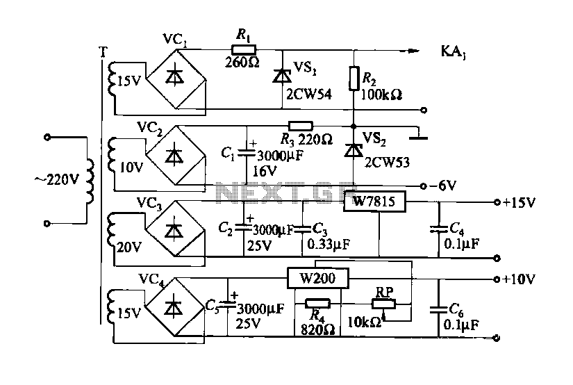
Overall, this CMOS circuit design integrates various components to form a cohesive system that ensures accurate timing and control for spot welding applications, making it adaptable for different welding requirements.Constitute a CMOS circuit time adjustment of a spot welder The number of cycles it uses CMOS device composed of a control circuit, optionally in the range of 1 to 99 cycles to choose from. In actual use, most of them within 10 cycles adjusted enough. Drawing, are integrated with CMOS circuitry; gates 1 to 20 available C036; C180 counter available 21,22; D flip-flops 25, 26 Available C043; seven segment decoder applications C036; LED digital works BS202.
Related Circuits
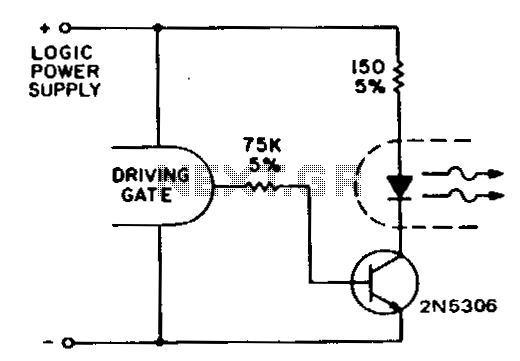
Standard CMOS logic operates with supply voltages as low as 3 V and is specified for a maximum current sinking/sourcing capability of 30 pA. To drive the infrared emitting diode (IRED) when utilizing CMOS to control an optocoupler, it...
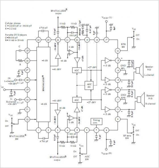
AN12979A is a stereo BTL amplifier that includes an AGC circuit to prevent clipping at the speaker output. This integrated circuit (IC) can perform mode changes via the I2C bus control system, allowing for functions such as toggling the...
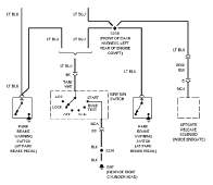
The following circuit illustrates the wiring diagram and electrical circuit troubleshooting for the 1997 Chevrolet Blazer. Features include a 4.3-liter Vortec V-6 engine, an AM-FM stereo radio with CD player, rear-wheel drive managed by a four-speed automatic transmission, air...

This is a design for a scoring game circuit suitable for any occasion where dice are used. The circuit utilizes a NE555 timer, a 74LS192 counter, a 74LS247 decoder, and a seven-segment LED display. The timer IC1 generates a...
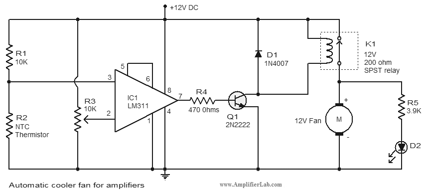
An automatic cooler fan for amplifiers is a circuit designed to conserve power in amplifier circuits. This circuit activates the fan. The automatic cooler fan circuit for amplifiers operates by utilizing temperature sensors to monitor the heat generated by the...
By utilizing a high-gain, high-impedance operational amplifier, it is possible to construct a long time delay circuit using a resistor-capacitor (RC) configuration, as it allows for high... An operational amplifier (op-amp) is a versatile component widely used in electronic circuits,...
Warning: include(partials/cookie-banner.php): Failed to open stream: Permission denied in /var/www/html/nextgr/view-circuit.php on line 713
Warning: include(): Failed opening 'partials/cookie-banner.php' for inclusion (include_path='.:/usr/share/php') in /var/www/html/nextgr/view-circuit.php on line 713