
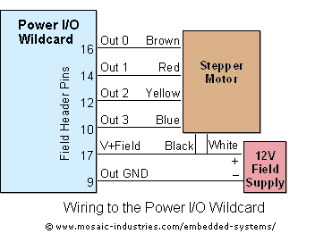
Controlling Stepper Motors Using Power IO Wildcard MOSFET Driver
The described system effectively manages multiple stepper motors, allowing for precise control over their operation. The architecture involves a central processing unit (CPU) that handles the timing and execution of motor steps through interrupts. Each motor's stepping behavior is governed by the defined parameters, including the maximum number of motors and the stepping speed, which can be adjusted based on the application requirements.
The signed 32-bit step counter serves as a critical component for tracking motor position and direction. This feature is particularly useful in applications requiring accurate positioning and movement. The ability to reset the step counter during specific operations, such as homing, enhances the flexibility of the system, allowing for recalibration as needed.
The direction constants and motor state tracking ensure that the system can accommodate various motor configurations and vendor differences. This adaptability is vital for integrating different stepper motors into the same control system, promoting versatility in design.
The interrupt-driven architecture provides efficient processing, allowing the CPU to manage multiple motors simultaneously while minimizing processing overhead. This design choice is essential for applications where real-time performance is critical, as it enables the system to respond promptly to changes in motor state or command inputs.
Overall, the described stepper motor control system is a robust solution for applications requiring precise motor control, with features that allow for customization and adaptability to various motor types and operational requirements.For maximum efficiency, set MAX_STEPPERS equal to the number of stepper motors that you are controlling (but never more than 4). Motors are referred to by their indices 0, 1, 2 and 3. On the QCard there is a trade-off between the number of motors being controlled and the maximum stepping speed, limited by the available processing power of the 68HC11.
Given that each interrupt-driven step requires 120 µsec per motor, while all 4 motors are stepping at their maximum speeds (1000 steps or half-steps per second in this application), the 68HC11 processor is busy about 50% of the time managing the motion via the low-level interrupt-driven utilities. Thus most applications would either use fewer motors or would raise the value of the MSEC_PER_TICK constant to decrease the maximum attainable speed of each motor.
The PDQ Board has a more powerful processor, so using four motors at 1000 full- or half-steps per second consumes only 8% of the PDQ Board`s processing capability. A useful parameter in the stepper status structure is the signed 32-bit step counter that keeps track of the step count over a range of ±2, 147, 483, 647 counts.
Positive values represent clockwise rotation, and negative values represent counter-clockwise rotation. The Step_Count function returns a 32-bit pointer to this 32-bit variable in common RAM; it accepts the motor index as the input parameter.
The Revolutions function in the demo program shows how to read and write this value. If the motor is stopped, the step count will not change during the interval. You can set the step counter to any value you want as long as the specified motor is not moving. For example, if you perform a HOME operation in which a microswitch is used to detect the home position of stepper motor 0, you could then set the motor`s step count to zero. If the motor is configured for full stepping, the count indicates the number of full steps that have been taken since the status array was initialized or since the step counter was last zeroed.
If the motor is configured for half stepping, the count indicates the number of half-steps that have been taken. In each case the counter is a signed 32-bit value. To calculate the total number of revolutions, simply divide the step counter by the number of steps (or half-steps) per revolution for your motor.
The default stepper motor provided by Mosaic has 200 full steps or 400 half-steps per full 360 ° revolution. The specified direction constants are CW (clockwise) =1, and CCW (counter-clockwise) = 1. Note that stepper motors purchased from different vendors may be wired differently internally, and the most common difference is that they spin in the opposite direction than the default motor supplied by Mosaic.
If this happens with a custom-specified motor, the simplest fix is to define new direction constants that have the opposite values compared to the default (that is, swap the 1 and 1 values). Another useful parameter in the stepper status structure is the byte that keeps track of the motor state.
This variable is controlled by the interrupt-driven control functions, so to the application program it is a "read-only" parameter. The pre-coded Motor_State function returns the value that encodes the state. Pre-defined constants MOTOR_STOPPED (value 5), and MOTOR_AT_FINAL_SPEED (value 1) are useful for detecting when the motor is stopped or has reached the specified terminal speed, respectively.
The Revolutions function in the demo program illustrates how this function is used. After a command such as Steps_At_Speed is executed, the background (that is, interrupt-driven) code sets up the ramp data structures which will control the motor to carry out the specified action. But note that the command (Steps_At_Speed in this example) finishes well before the stepper motor 🔗 External reference
Related Circuits
If you are looking at this page, you probably feel like I did when I tried to run a self-powered PIC programmer with my notebook computer. Yes, the serial port was the ultra-low-power type and wouldn't provide enough current...
The following segment provides the enhanced Motorola schematic for a typical application of the MRF141G, which includes parasitic stabilization features. The MRF141G is a broadband power RF MOSFET capable of delivering a conservatively rated 300 watts across the FM...
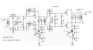
This is an RF Power Amplifier designed for low-cost QRP applications. The circuit operates over a broadband frequency range of 1.8 to 30 MHz, eliminating the need for tuning. The only adjustment required is to set the quiescent current...
This circuit functions as a low-frequency warning device. The output from the oscillator generates a square wave signal, which is utilized to operate lamps or small relays. The circuit alternately flashes two incandescent lamps. The low-frequency warning device circuit typically...
Build a large dancing robot. This was intended to be a walking robot, but it ended up moving in a more rhythmic manner. A video is available in the last step. The project involves the construction of a large dancing...
This regulated power supply was built as a simplified outboard version of a PSU in my first phono stage. Replacing hexfreds with tube rectifier eliminates the need for power-on sequencing. Chassis (salvaged from a hospital laser PSU) size is...