
Converting an EV PL-76 or 1776 microphone to p48 powering

The circuit described involves several key components that must be carefully integrated for proper functionality. Resistors rated at 1/8 watt are adequate for most applications, ensuring they can handle the current without overheating. The zener diode's power rating, whether 250 mW or 1W, should be selected based on the specific voltage regulation requirements of the circuit. The electrolytic capacitor’s flexibility in capacitance and voltage rating allows for optimization based on available space and desired performance, but it is crucial that its dimensions allow it to fit within the designated battery compartment.
To prepare the vectorboard, precise cutting is essential to ensure a snug fit within the battery compartment. The use of tin snips or a scoring technique provides options for achieving the desired dimensions. Once the vectorboard is prepared, the assembly process involves inserting component leads through the board and bending them to create a compact layout, similar to that of a printed circuit board. This method enhances the reliability of solder joints and minimizes the risk of short circuits.
Soldering requires careful attention to detail, particularly when connecting multiple component leads. Ensuring that leads do not cross inappropriately and that solder joints are clean and secure is vital for circuit integrity. Accessing the connector is a critical step in this process. The locking screw mechanism of the Switchcraft insert is designed for secure connection, and care should be taken to avoid damaging the pins during disassembly. Proper soldering of the wires to the vectorboard is necessary to maintain connectivity and functionality of the circuit.
Once the circuit is fully assembled and the connector is reinserted, securing the locking screw ensures that the connection remains stable during operation. This comprehensive approach to building the circuit on vectorboard allows for a reliable and efficient design that meets the specified requirements while fitting within the physical constraints of the battery compartment.The resistors could be 1/8w, The zener diode could be a 250mW part, or it could be a 1W part (1N number will be different). The electrolytic capacitor is plain vanilla, and the value can deviate (larger is ok, higher voltage is ok), but when it`s all done, it has to fit inside the battery compartment.
Cut a piece of vectorboard that fits across the flats of the battery compartment. Tin snips work just fine. Lacking that, you can score the board by dragging a sharp knife across the perfs several times, then flex the board against the cut marks to encourage it to break along the scoring. Build the circuit on the vectorboard. Fasten with tape. To build a circuit using Vectorboard, push the leads through the board, then bend them flat against the board, bending them to approximate a printed circuit board.
Lay the leads of different components across each other and solder. You`ll need to access the connector. Locate the connector`s locking screw at the end of the microphone. Turn the screw counterclockwise to loosen it. This is a Switchcraft insert, so the screw retracts INSIDE the connector, and you can now grab one of the pins with a pair of pliers and gently pull it loose (lest you break the wires attached to it). Now you can solder the wires going to the vectorboard to pins 1, 2, and 3. Then thread the wires back into the battery compartment and reinsert the connector insert. Remember to lock the connector in place by turning the insert screw clockwise. 🔗 External reference
Related Circuits
Many antique radios operate on batteries, including tube portables like the Zenith model K-401 and "farm" radios used in rural areas without electrical power. This article provides historical context on battery usage in early radios and offers guidance on...
Well, it's pretty much a PAiA preamp - usual input circuitry followed by one half of dual op-amp rigged in fixed 20dB amplification circuitry, followed by second stage which is adjustable for up to 40dB amplification, for up to...
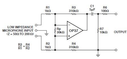
This microphone preamp schematic is an electronic circuit project utilizing the OP37 operational amplifier from Analog Devices. It functions as a fixed-gain transformerless microphone preamp, amplifying differential signals from low-impedance microphones by 50 dB, with an input impedance of...
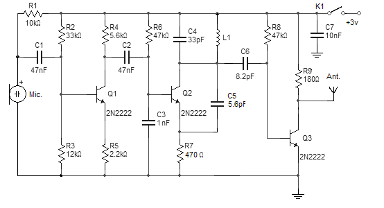
This FM wireless microphone is straightforward to construct and offers significant transmission capabilities, with a range of approximately 300 meters outdoors. Its compact component count and 3V operating voltage allow it to effectively penetrate multiple floors of an apartment...
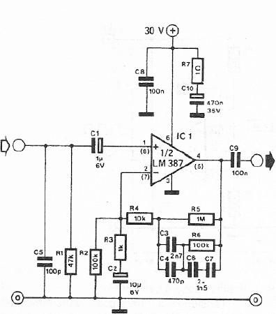
A dynamic microphone preamplifier can be constructed using the LM387 dual operational amplifier integrated circuit. The input impedance is approximately 47k ohms, primarily determined by resistor R1. If a dynamic microphone with a different impedance is to be connected,...
This preamplifier amplifies the signal from a microphone, an amplifier so that it can be further strengthened. The circuit supplies an output signal line. With two transistors, it is not difficult to build such a circuit. The amplifier produces...
Warning: include(partials/cookie-banner.php): Failed to open stream: Permission denied in /var/www/html/nextgr/view-circuit.php on line 713
Warning: include(): Failed opening 'partials/cookie-banner.php' for inclusion (include_path='.:/usr/share/php') in /var/www/html/nextgr/view-circuit.php on line 713