
crystal controlled fm transmitter
The crystal-controlled FM transmitter circuit is designed to generate frequency-modulated signals with high stability and precision. At the core of the circuit is the crystal oscillator, which serves as the frequency-determining element. The crystal's cut and characteristics dictate the operational frequency of the transmitter, ensuring minimal drift and maintaining signal integrity.
The output of the crystal oscillator feeds into the modulation stage, where audio signals are combined with the carrier wave. This modulation can be achieved using a variety of methods, including direct modulation or through the use of a modulator IC. The choice of modulation technique impacts the quality and fidelity of the transmitted audio.
Following the modulation stage, the signal is routed to a series of power amplifier stages. These amplifiers are crucial for boosting the signal strength to a level suitable for transmission over longer distances. Typically, a class A or class C amplifier configuration is employed, depending on the desired efficiency and linearity of the output signal. Careful selection of components, including transistors and passive elements, is essential to optimize performance and minimize distortion.
Additionally, the circuit may include filtering stages to remove unwanted harmonics and ensure compliance with regulatory standards for frequency transmission. Bandpass filters can be used to allow only the desired frequency range to pass through while attenuating out-of-band signals.
For antenna coupling, an impedance matching network is often implemented to maximize power transfer from the transmitter to the antenna. This network ensures that the transmitter operates efficiently and reduces the risk of damage due to reflected power.
Overall, the crystal-controlled FM transmitter circuit is a sophisticated design that balances stability, power, and signal quality, making it suitable for various applications in communication and broadcasting.Circuit of a crystal controlled FM transmitter or crystal transmitter. The circuit is using crystal oscillator and some power amp stages to increase output power. .. 🔗 External reference
Related Circuits
This is a relay circuit that detects the presence of sound to activate the relay. This sound-controlled relay can be utilized as a voice-operated switch or for controlling lights. The sound-activated relay circuit typically employs a microphone or a sound...
This circuit generates audio musical notes that can be heard from a distance of up to 10 meters. It consists of two main components: an infrared (IR) music transmitter and an IR music receiver. The IR music transmitter operates...
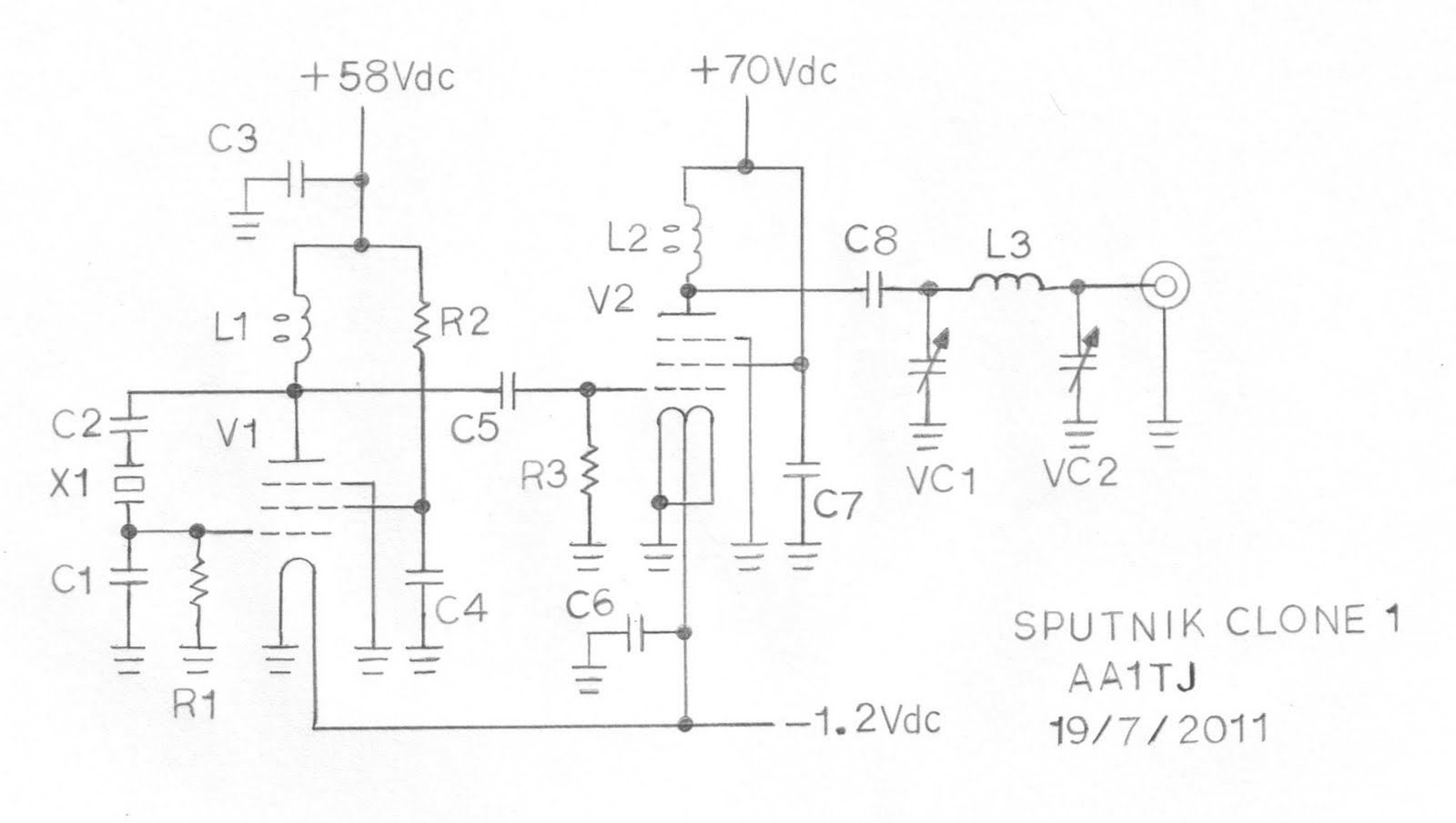
This document describes a prototype transmitter for the Sputnik QSO Party. The RF output power is 450 mW, with 70 V DC at 14.4 mA on the V2 anode. The screen current (G2) for V2 is 1.6 mA, while...
The circuit of an AM transmitter is designed to transmit amplitude modulated (AM) double sideband (DSB) signals. A modulated AM signal consists of a carrier and two symmetrically spaced sidebands. The two sidebands have the same amplitude and carry...
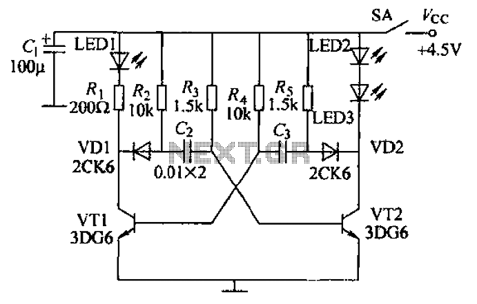
Transistors VT1, VT2, and associated RC components are configured to form a multivibrator. The multivibrator operates with resistors Ra and R4 serving as base bias resistors for VT2 and VT1, respectively. When the switch SA is closed after applying...
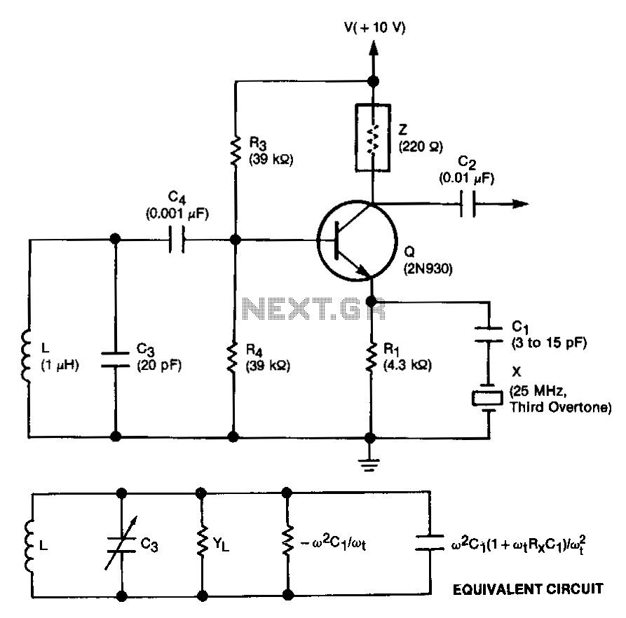
This unit is easily tunable and stable, consumes minimal power, and is more cost-effective than other types of oscillators that operate at similar frequencies. This unique combination of features is made possible by a design concept that involves operating...