
Crystal Oscillator
The crystal oscillator circuit utilizes the properties of a quartz crystal to generate a stable frequency output. The op-amp serves as the active element that provides the necessary gain and feedback for oscillation. In this configuration, the crystal is connected in a feedback loop with the op-amp, allowing it to determine the oscillation frequency based on its physical characteristics.
The circuit typically includes several key components: the op-amp, the crystal, resistors, and capacitors. The op-amp is configured in a non-inverting amplifier mode to ensure that the output signal is of the same phase as the input, which is critical for maintaining oscillation. The crystal is connected in parallel with a capacitor to form a resonant circuit that defines the frequency of oscillation.
Resistors are used to set the gain of the op-amp and to limit the current through the crystal, protecting it from excessive power that could lead to damage. Additionally, bypass capacitors may be included to stabilize the power supply and reduce noise in the circuit.
The output of the op-amp provides a sinusoidal waveform, which can be further processed or used directly as a clock signal for various applications in digital electronics. The frequency stability and low phase noise characteristics of this oscillator make it suitable for use in communication systems, microcontroller timing applications, and other electronic devices requiring precise frequency generation.
Overall, this low-frequency crystal oscillator circuit exemplifies the practical application of op-amps in generating stable and reliable oscillations, leveraging the inherent properties of quartz crystals.Crystal oscillator, especially the low frequency one, can be easily implemented using op-amp as the amplifier. Here is the schematic diagram of such circuit:.. 🔗 External reference
Related Circuits
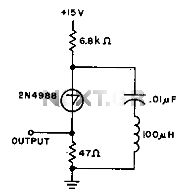
The capacitor charges until the switching voltage is reached. When the switch (SUS) is activated, the inductor causes the current to oscillate. When the current through the switch drops below the holding current, the device turns off, and the...
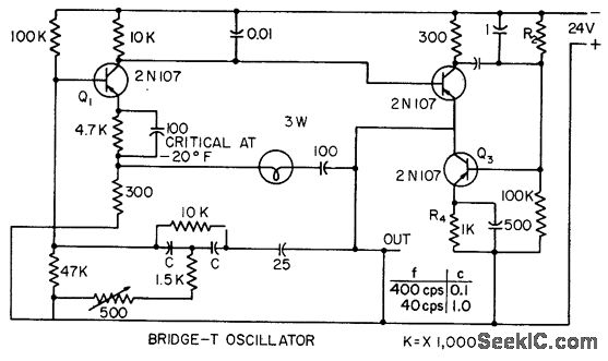
This circuit incorporates heavy degenerative feedback, utilizing a small lamp as a nonlinear compensating resistance. It provides a constant output frequency and voltage for supply voltages ranging from 12 to 32 V, and operates effectively at temperatures as low...
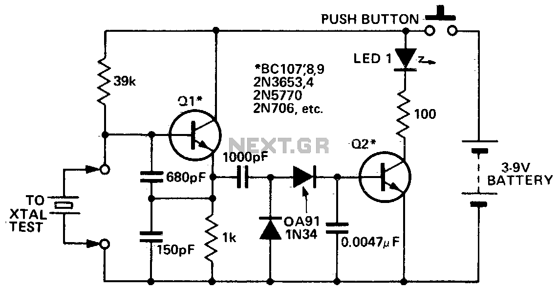
This circuit is designed to check fundamental oscillations. When Q2 conducts, the LED lights up. It operates with A3 HF crystals on a "Go-No-Go" basis. An untuned or 6V, 40mA bulb can be used in place of the Colpitts...
The Wien-bridge oscillator consists of an operational amplifier (OA) in a non-inverting configuration with a gain of 1 + R2/R1 and an RC feedback network. The Wien-bridge oscillator is a type of electronic oscillator that generates sine waves. It employs...
To achieve a 50% duty cycle using a 555 timer IC, two diodes can be employed to isolate the charging and discharging paths. Alternatively, it is also possible to configure the circuit without diodes. The 555 timer IC is a...
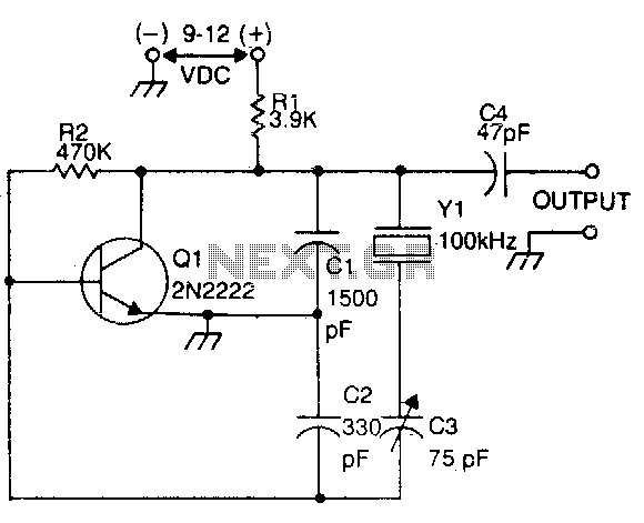
This circuit is commonly utilized by amateur radio operators, shortwave listeners, and various users of shortwave receivers to calibrate the dial pointer. The oscillator functions at a fundamental frequency of 100 kHz, with its harmonics employed to identify specific...