
crystal oscillator discreet pierce oscillator
The Pierce oscillator is a fundamental component in many electronic systems, particularly where precise timing and frequency generation are essential. The configuration typically consists of a crystal, a transistor (or operational amplifier), and passive components such as resistors and capacitors. The crystal serves as a frequency-selective element, defining the oscillation frequency with high precision.
In a discrete Pierce oscillator, the transistor is configured in a common-emitter arrangement, which provides the necessary gain for oscillation. The feedback loop is established through the crystal and the passive components, which ensure that the total phase shift around the loop equals 360° at the desired frequency. The careful selection of R1 and C1 is critical, as these components determine the phase delay that allows for sustained oscillations.
The crystal's impedance characteristics play a significant role in the oscillator's performance. The series resonance of the crystal provides a low impedance path at the oscillation frequency, while the load components help to stabilize the oscillation. The combination of the crystal's inherent Q factor and the additional phase lag introduced by C2 enhances stability and reduces the susceptibility to noise and variations in power supply.
Overall, the Pierce oscillator is favored for its simplicity, cost-effectiveness, and reliability in generating stable frequencies across a wide range of applications, including clock generation in digital circuits, RF transmission, and audio signal processing. Its design principles can be adapted for various frequency ranges and power requirements, making it a versatile choice for engineers in the field of electronics.Although there are many different configurations for Crystal Oscillators, the most common are the discrete and integrated circuits Pierce and environment RLC Bridge. When needed very good frequency stability and reasonably simple circuits, the discrete Pierce is a good choice.
When your main concern is the low cost and the ability of a simple digital interface will suffice with a Pierce oscillator using IC. However, to the best frequency stability, the half bridge is the best option RLC. The discrete crystal oscillator Pierce has many advantages. Its operating frequency spans the full range of basic glass (from 1 kHz to about 30 MHz). Uses simple circuits that require relatively few components (most frequently versions require only one transistor half). The Pierce oscillator design develops high power output signal while dissipating little power in the same crystal.
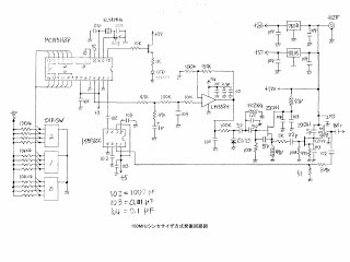
Finally, the stability of frequency in the short term Pierce crystal oscillator is excellent (this is because in the input circuit of load Q is nearly as high as the internal Q of the crystal). The figure shows a circuit for a discrete Pierce oscillator 1 MHz Q1 provides all the necessary gain self oscillations to occur.
R1 and C1 provide a phase delay of 65 ° to the feedback signal. The impedance of the crystal is basically a small resistive inductive component. This impedance reactor combined with C2 provides additional 115 ° phase lag. Transistor inverts the signal (180 ° phase shift), by providing 360 ° required for total phase change to the circuit. Because the load is mainly non resistive glass (mostly the series combination of C1 and C2), this type of oscillator provides very good frequency stability in the short term.
🔗 External reference
Related Circuits
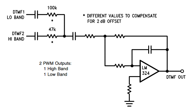
DTMF (Dual Tone Multiple Frequency) is associated with digital telephony, and provides two selected output frequencies (one high band, one low band) for a duration of 100 ms. DTMF generation consists of selecting and combining two audio tone frequencies...
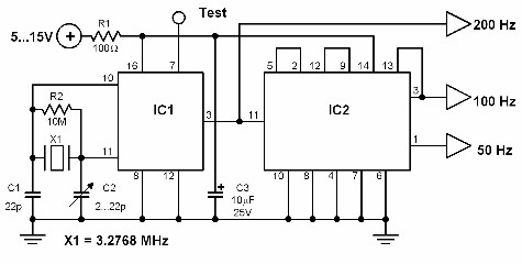
This circuit generates a 50 Hz timebase signal that is independent of the power line frequency. It is designed to provide the 50 Hz signal for electronic circuits that operate specifically with this clock frequency, primarily for circuits and...

Q is the transistor, L1 and L2 form a resonant circuit, with L2 also serving as a feedback network. The feedback voltage is transmitted to the transistor base through the coupling capacitor Cb. Figure 2 illustrates the communication channel,...
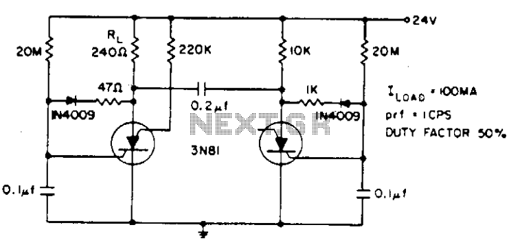
Electrolytic capacitors are not required to generate a 1 cps frequency. When the silicon-controlled switch (SCS) is triggered, the 0.2 µF commutating capacitor deactivates the other capacitor and charges its gate capacitor to a negative potential. The gate capacitor...
This MOT's LSI is highly suitable for designing VFOs in ham radios, featuring a 4-digit BCD preset counter with a range from 3 to 3999. It also includes a standard crystal frequency oscillator and preset dividers. The input nodes...
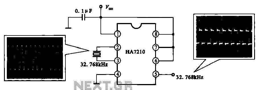
This circuit illustrates a 32.768 kHz micro-power clock oscillator, suitable for use in mobile phones, laptop computers, and home appliances. It generates a clock signal that can be utilized in various applications. The 32.768 kHz micro-power clock oscillator circuit is...
Warning: include(partials/cookie-banner.php): Failed to open stream: Permission denied in /var/www/html/nextgr/view-circuit.php on line 713
Warning: include(): Failed opening 'partials/cookie-banner.php' for inclusion (include_path='.:/usr/share/php') in /var/www/html/nextgr/view-circuit.php on line 713