
Crystal Set 1
The P-C70-A circuit from Antique Electronics Supply is designed for optimal performance in radio frequency applications. The circuit configuration allows for the integration of various components, including manually wound coils or commercially available ferrite antennas. When constructing the coil, the use of double-sided tape is a practical solution to maintain wire tension during winding, which is crucial for achieving a stable inductive component.
In terms of connectivity, the circuit layout specifies the use of color-coded wires for clarity: the white wire for the antenna connection and the black wire for earth ground. The variable capacitor, a critical component for tuning, is connected to the large green winding. Its ground terminal is linked to the yellow wire, while the stationary terminal connects to the green wire, ensuring proper operation of the tuning mechanism.
The integration of a crystal diode is essential for signal rectification, where the blue wire connects to the diode and the red wire serves as the circuit ground. This arrangement facilitates the conversion of the radio frequency signal into a usable audio signal.
For users utilizing a ferrite rod antenna, the same principles of magnetic coupling apply. The ferrite rod serves as an efficient medium for enhancing the antenna's inductance, and the tuning capacitor is connected in a manner consistent with its original configuration in a transistor radio, ensuring optimal resonance and signal quality.
The inclusion of a 33 pF capacitor between the primary and secondary windings in the circuit designed for the Hammond antenna coil significantly boosts sensitivity. This capacitor, in conjunction with the coil, enhances both the capacitively and magnetically coupled signals, leading to improved voltage output. This circuit design also accommodates modern stereo headphones, making it versatile for various listening applications.
Overall, the P-C70-A circuit offers flexibility and adaptability for enthusiasts and engineers alike, whether they choose to wind their own coils or utilize pre-made components. The detailed instructions and configurations provided ensure a comprehensive understanding of the circuit's operation and potential applications in radio frequency technology.The P-C70-A from Antique Electronics Supply works just as well and maybe a little better than the coils you can wind. Winding coils is an interesting experiment and you may want to do it just for the fun of it. If you would rather skip all the fun you can. An additional circuit has been added below. It`s really not that hard and it is guaranteed to be painless. I have devised a method in which you use Double Stick (stickem on both sides) Scotch Tape to hold the wire in place while you wind the coil. One of the most frustrating things about winding a coil is what happens when you let go of it. The double stick tape prevents this from happening. To learn how to wind your own coils click here. If you don`t have a variable capacitor you will need to buy one. If you would rather not wind your own coils there are ferrite antennas and antenna coils for sail. Click here to learn what to buy and where to buy it. Another source is to take a transistor radio apart to salvage the tuning capacitor and ferrite antenna. It`s kind of fun tearing up one of those disgusting little things and you might learn a thing or two in the process.
The parts you get are of limited usefulness which is why I really don`t recommend it. If you have the time and the inclination give it a try. Just click here. If you wound your own coil here is how to connect it. The double dashed line is a symbol indicating that the coils are coupled magnetically. The relative position of the coils in the diagram has no relationship to the actual physical position of the coil windings. The antenna connects to the white wire and the earth ground connects to the black wire. The variable capacitor is connected to the large green winding as follows. The ground terminal of the capacitor connects to the yellow wire and the terminal to the stationary part goes to the green wire.
The blue wire goes to the crystal diode and the red wire goes to circuit ground. If you bought a ferrite rod antenna or salvaged one from a transistor radio here is how to use it. The double dashed line is a symbol for the ferrite rod. The relative position of the coils in the diagram has no relationship to the actual physical position of the coil windings. The antenna and earth ground are connected to the wire you wound around the ferrite rod antenna. The tuning capacitor from the radio is connected to the large winding of the ferrite antenna. The ground terminal of the capacitor connects to the ground end and the terminal which originally connected to the resonating winding connects there again.
In other words the antenna and tuning capacitor are connected together exactly the way they were in the radio. The base winding connects to the "crystal" diode. If you decided to buy the Hammond antenna coil from AES here is the circuit to use it in. This new circuit also includes a way to use modern stereo headphones. The 33 pf capacitor between the primary and secondary considerably enhances the sensitivity. The capacitively coupled signal adds to the magnetically coupled signal and in addition the cap and coil form a series resonance a little below the parallel resonant frequency.
This gives a considerable boost in the voltage. I have received many emails asking if mo 🔗 External reference
Related Circuits

This circuit operates effectively across a broad frequency spectrum. XTAL 1 serves as a fundamental-frequency crystal. Tl and CI are adjusted to match the input frequency. This circuit can be utilized as a straightforward shortwave converter for AM radios,...
The concept of a "crystal radio" is typically linked with large antennas and radio broadcasting on long and medium bands. This article discusses experimentally tested detector circuits for VHF receivers designed to listen to FM stations. The discovery of...
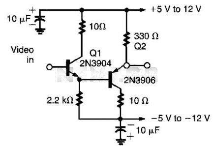
This circuit has demonstrated effectiveness as a video buffer and can easily drive a 75-ohm load to a 1.5-V peak-to-peak output. The bandwidth exceeds 20 MHz, and the DC offset is less than 0.05 V, attributed to the difference...
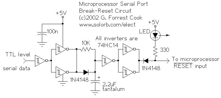
This circuit enables a remote microprocessor to reset the control of a host by sending an interrupt signal over an RS-232 or RS-422 serial line. When the remote machine is restarted using a simple program loader, it may cause...
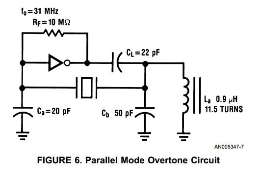
With the advent of high speed HCMOS circuits, it is possible to build systems with clock rates of greater than 30 MHz. The familiar gate oscillator circuits used at low frequencies work well at higher frequencies and either LC...
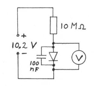
Diodes with a low voltage drop also exhibit a high reverse current (leakage current), which places a heavier load on the detector circuit, reducing the quality factor (Q) of the circuit and consequently lowering the voltage across the LC...
Warning: include(partials/cookie-banner.php): Failed to open stream: Permission denied in /var/www/html/nextgr/view-circuit.php on line 713
Warning: include(): Failed opening 'partials/cookie-banner.php' for inclusion (include_path='.:/usr/share/php') in /var/www/html/nextgr/view-circuit.php on line 713