
Crystal-timebase
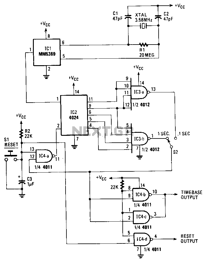
An on-board oscillator and a 17-stage divider comprise IC1. By connecting a standard 3.58-MHz television color-burst crystal as illustrated, a precise source of 60-Hz square waves is generated at the output of IC1, pin 1. These pulses are subsequently fed to IC2, a 4024 seven-stage ripple counter. The outputs of IC2 are connected to various gates in IC3, which is a dual four-input NAND gate. Depending on the position of the pulse-select switch S2, one of the gates will provide an output/reset pulse of the selected width.
The circuit design features an on-board oscillator integrated with a 17-stage frequency divider, identified as IC1. The oscillator utilizes a 3.58-MHz television color-burst crystal, which is a common frequency reference in television applications, ensuring a stable and accurate oscillation. The output from IC1 generates 60-Hz square waves, a frequency commonly used in timing applications, particularly in synchronizing circuits.
The generated square waves are fed into IC2, a 4024 seven-stage ripple counter. This counter divides the frequency of the incoming pulses, allowing for the generation of multiple output frequencies based on the original 60-Hz signal. The outputs from IC2 can be utilized for various timing and control applications, providing versatility in circuit design.
IC3, which consists of a dual four-input NAND gate, receives the outputs from the ripple counter. NAND gates are fundamental building blocks in digital electronics, known for their versatility and ability to perform various logical functions. The configuration of IC3 allows for the selection of specific outputs from IC2 to be used for further processing.
A pulse-select switch, designated as S2, is incorporated into the design to enable the selection of different output widths from the NAND gates. Depending on the position of switch S2, a specific gate within IC3 is activated to provide an output/reset pulse. This feature allows for customizable pulse widths, enhancing the circuit's adaptability for different applications or requirements.
Overall, this circuit exemplifies a practical application of digital logic components and frequency division, providing a reliable method for generating variable pulse widths from a stable frequency source. The design is suitable for various electronic applications where precise timing and control signals are essential.An on-board oscillator and a 17-stage divider compose IC1. By connecting a standard 3.58-MHz, television color-burst crystal as shown, an accurate source of 60-Hz squarewaves is generated at the IC"s output, pin 1. Those pulses are then fed to IC2, a 4024 seven-stage ripple counter. Its outputs are connected to different gates in IC3, which is a dual four-input NAND gate. Depending on which position pulse-select switch S2 is on, one of those gates will provide an output/reset pulse of the selected width. 🔗 External reference