
Current-collector head-amplifier
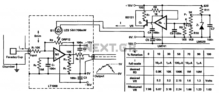
To amplify small current signals, such as those from an electron collector inside a vacuum chamber, it is beneficial for reasons related to noise and bandwidth to utilize a "head amplifier" connected to the chamber. The operational amplifier N1 is a precision bipolar device characterized by extremely low bias current and offset voltage, as well as low noise, which facilitates the use of a 100:1 feedback attenuator formed by resistors R4 and R5. The resistance of resistor R3 can be adjusted from above 10 MΩ to below 1 Ω, allowing the nominal output signal of 0 to 1 V peak to correspond to input current ranges of 1 nA to 10 µA, entering through the protective resistor R1. Illumination from bulb B1 is directed onto R3, with the filament current I regulated by operational amplifier N2. The reference voltage VR is shaped by resistors R9 and R10 to customize the bulb and light-dependent resistor (LDR) characteristics to the intended current ranges. Consequently, rotating the calibrated knob adjusts the resistance of R3 to align with the peak current scale indicated.
The circuit described functions as a sensitive current amplifier, ideal for applications requiring precise measurements of low-level signals. The operational amplifier N1 is central to the design, providing the necessary gain while minimizing noise and distortion. Its low bias current and offset voltage characteristics ensure that the amplification process does not introduce significant errors, making it suitable for detecting minute currents from the electron collector.
The feedback network, consisting of resistors R4 and R5, establishes a 100:1 attenuation ratio, enabling fine control over the amplification factor. This configuration allows for a wide dynamic range of input currents to be effectively processed. The adjustable resistor R3 plays a critical role in scaling the output voltage, which is directly related to the input current. By varying R3 from high resistance (above 10 MΩ) to low resistance (below 1 Ω), the circuit can accommodate a broad spectrum of current inputs, thus enhancing its versatility.
The protective resistor R1 is crucial for safeguarding the circuit against excessive currents that could potentially damage sensitive components. Additionally, the illumination from bulb B1 serves a dual purpose: it not only provides the necessary light for the LDR but also helps in visually indicating the operational status of the circuit.
Operational amplifier N2 serves to regulate the filament current I, which influences the brightness of bulb B1. This regulation is vital for maintaining consistent performance of the LDR, ensuring that the response characteristics remain stable across varying conditions. The shaping of the reference voltage VR through resistors R9 and R10 allows for further customization of the circuit's response to different current ranges, facilitating precise calibration.
Overall, this circuit configuration exemplifies a well-engineered solution for amplifying small current signals in environments where noise and bandwidth are critical factors, making it an effective tool for various scientific and industrial applications.To amplify small current signals such as from ah electron-collector inside a vacuum chamber, it is convenient for reasons of noise and bandwidth to have a "head-amplifier" attached to the chamber. The op amp N1 is a precision bipolar device with extremely low bias current and offset voltage (1) as well as low noise, which allows the 100:1 feedback attenuator R4:R5.
The resistance of R3 can be varied from above 10M to below 1R, and so the nominal 0 to 1 V-peak output signal corresponds to input current ranges of 1 nA to 10 µ; this current i enters via the protective resistor Rl. Light from the bulb B1 shines on R3, and the filament current I is controlled by the op amp N2. The reference voltage VR is "shaped" by the resistors R9R10 so as to tailor the bulb and LDR characteristics to the desired current ranges. Thus, rotation of the calibrated knob gives the appropriate resistance to R3 for the peak-current scale shown.
🔗 External reference