
Custom Arduino circuit not working
The described circuit consists of several key components: a keypad for user input, a servo motor for mechanical movement, and LEDs for visual feedback. The integration of these elements onto a single PCB is a common practice for creating compact and efficient designs. The Arduino Uno serves as the microcontroller, managing the inputs from the keypad and controlling the outputs to the servo and LEDs.
The keypad is typically connected to the Arduino using a matrix configuration, allowing multiple buttons to be read with fewer pins. Each button press can trigger specific actions, such as moving the servo to predefined positions or turning the LEDs on and off. The servo motor, which is powered by the circuit, is expected to respond to commands issued by the Arduino, moving to a designated angle upon initialization.
The red LED serves as an indicator, providing visual confirmation that the circuit is functioning as intended. When the circuit is powered, the LED should light up, signaling that the system is active. If the LED does not illuminate, it may indicate an issue with the circuit connections, the power supply, or the programming on the Arduino.
In the case where the servo is powered but does not perform the expected movements, it is essential to check the following: the programming logic in the Arduino code, the physical connections between the servo and the PCB, and whether the servo is correctly calibrated to respond to the commands issued. Additionally, it may be worthwhile to verify that the power supply is sufficient to meet the servo's operational requirements.
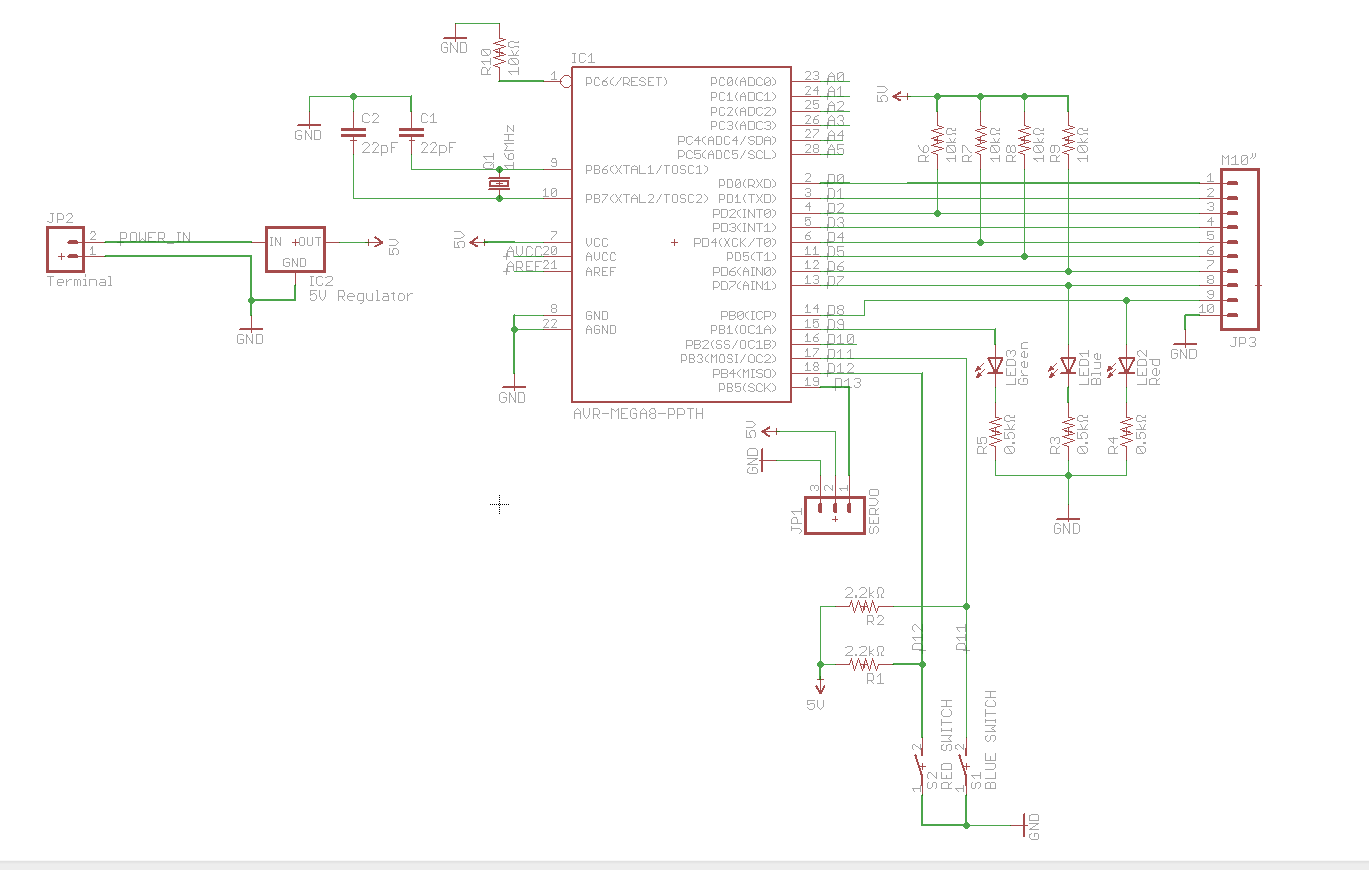
The design of the PCB should also be examined for potential issues such as short circuits, incorrect component placements, or insufficient grounding, which could affect the performance of the entire circuit. By addressing these factors, the functionality of the circuit can be restored, ensuring that both the LED and the servo operate as intended.A circuit using a keypad, a servo and a few LED`s. This was connected to my Arduino Uno. Now I tried putting everything onto a single PCB and thus building my own custom "Arduino" into it. The red LED is supposed to shine and the servo must move to a certain position upon startup, but it does not happen - the servo does get power and keeps it reacts in two ways: 🔗 External reference
Related Circuits
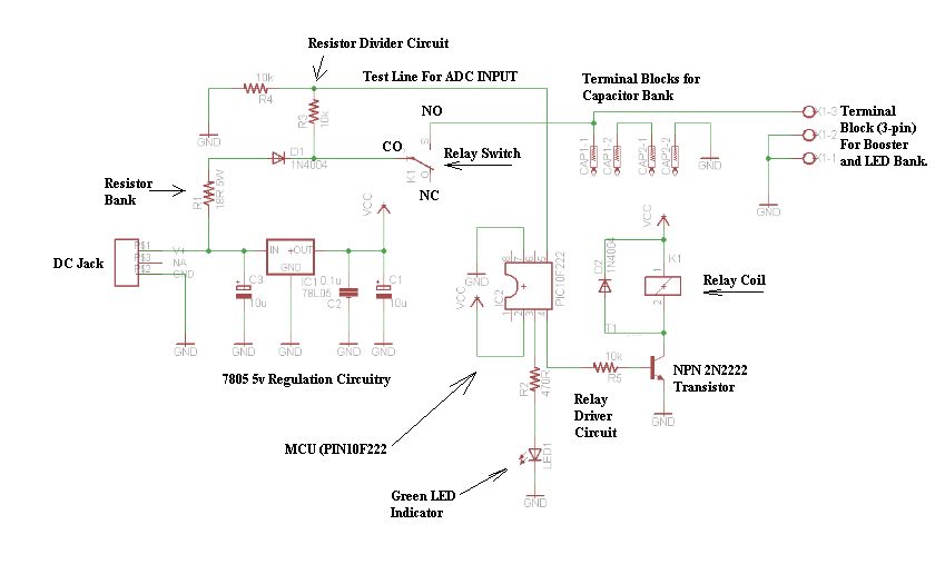
The schematic consists of four hardware blocks: 1) The wall transformer 2) The charging circuit 3) The control unit 4) The output stage. The circuit schematic is structured around four essential hardware blocks that facilitate the overall functionality of the...

Battery vampires are circuits designed to extract as much energy as possible from batteries or cells. They are not regulated drivers; rather, they are boost circuits that create a higher output voltage from a low input voltage and provide...
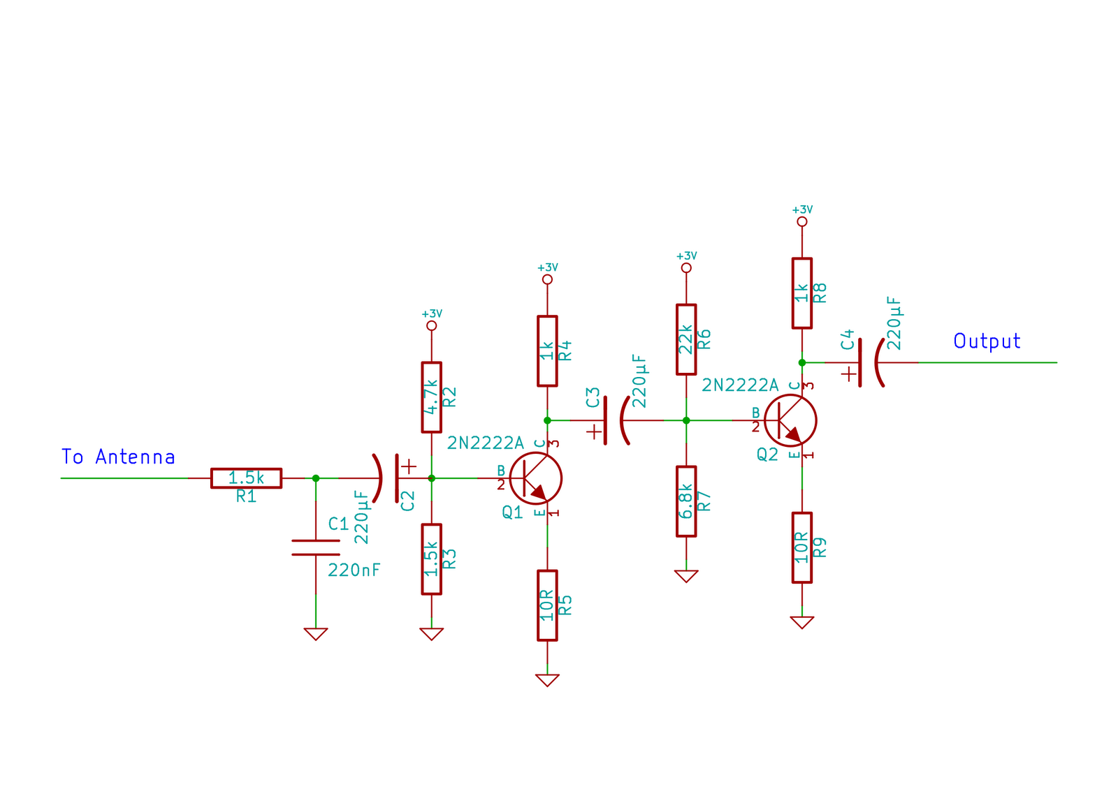
This circuit does not function as effectively as it could. It was created when the designer had a limited understanding of circuit design. An improved schematic will be developed and posted later, featuring a better design. The schematic indicates...
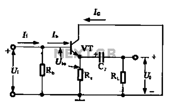
A common collector amplifier circuit can be analyzed through its DC and AC paths. The DC path provides a bias circuit for the power transistor, determining whether it is in an active or off state, primarily influenced by the...

This DC to DC converter increases a DC voltage to nearly double its original value and is useful for elevating the output voltage of solar batteries to the required level. The DC to DC converter operates on the principle of...
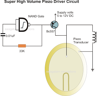
In the previous post, a piezo transducer element was discussed, along with its application in electronic circuits. This article will explore how a piezo transducer can be driven or operated using a simple circuit. The amplification method differs from...