
CVS Oral Thermometer Dissection
The described thermometer circuit is designed for ease of use and functionality, integrating multiple components to create a compact and efficient temperature measurement system. The central element is the integrated circuit (IC), which handles the majority of the processing tasks. The temperature probe is critical for measuring ambient temperature, and it interfaces directly with the IC to relay temperature readings. The output is displayed on an LCD, which is controlled via a 16-bit bus, ensuring precise data representation.
The inclusion of a buzzer provides an audible indication when temperature measurement is complete, enhancing user interaction. The circuit also features a normalizing reference circuit, which stabilizes the temperature readings by compensating for variations in the measurement environment. This is particularly important in applications where accurate temperature measurement is crucial.
Resistors R3 and R4, along with capacitor C1, form a part of the thermal measurement circuit, where they work together to establish the time constant of the circuit. This time constant is influenced by the characteristics of the variable thermal device, which can change its properties based on temperature fluctuations.
The role of components R2, C2, and C3, while not explicitly defined, is likely related to filtering or signal conditioning, ensuring that the signals processed by the IC are clean and accurate. The jumpers A and B provide a user-configurable option to switch between Celsius and Fahrenheit, allowing for adaptability based on user preference or regional standards.
Overall, the design represents a well-thought-out approach to creating a user-friendly temperature measurement device, with careful consideration given to both functionality and ease of use.This very simple high-level design demonstrates the product`s structure. Its integrated circuit responds to button presses and senses temperature via the probe, displaying the temperature on the LCD and sounding the buzzer when finished. This more detailed diagram shows that the temperature probe is part of a temperature measurement circuit.
There is also what appears to be a normalizing referenc circuit. Finally, this diagram incorporates the unit-selection jumper only visible on the PCB. This schematic illustrates the relative simplicity of this thermometer circuit; most of the work is done inside the IC. The themal device works with R3, R4, and C1 to make a temperature measurement circuit, with the variable thermal device affecting the circuit`s time constant.
The LCD is driven via a 16-bit bus, and the buzzer has a two-wire interface for sending pulses. The operation of R2, C2, and C3 is unapparent, but the waveforms on R1 seem to suggest that it provides a reference circuit for normalizing temperature measurements. The jumpers (disconnected pads) A and B can be used to switch the thermometer into Celsius. 🔗 External reference
Related Circuits

When the system is placed in a shop or mall, logos and product advertisements serve as an ideal complement to temperature information. For home use, photographs of children at the beach or, should the temperature drop, images of making...

Research has been conducted on a project aimed at enhancing understanding of electronics, networking, and programming. The project involves the construction of an online thermometer suitable for applications requiring temperature monitoring. The current work environment is a laboratory where...

The low output impedance of a closed-loop operational amplifier (op amp) provides ideal immunity to line noise, while the offset voltage drift of the op amp serves as a temperature sensor. Utilizing the op amp in this manner requires...

The circuit consists of the MAX1494 and a thermocouple temperature measurement system. The MAX1494 is terminated at 1N GND 5-32. An external temperature sensor, such as the DS75, can be utilized for junction temperature compensation. The MAX1494 employs an...
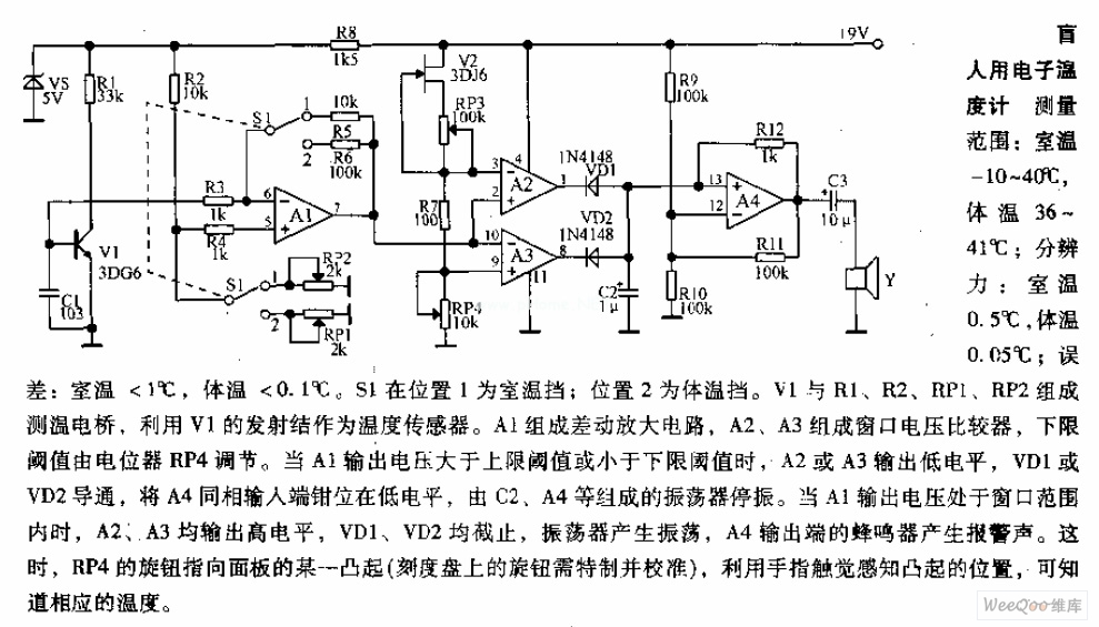
Measuring range: room temperature is -10 to 40 degrees Celsius; body temperature is 36 to 41 degrees Celsius; Resolution: room temperature is 0.5 degrees Celsius, body temperature is 0.05 degrees Celsius; error: room temperature <1 degree Celsius, body temperature <0.1 degrees Celsius. When switch S1 is in position 1, it displays the room temperature profile; position 2 displays the body temperature profile. Components V1, R1, R2, RP1, and RP2 form the temperature measurement circuit. The temperature measurement circuit is designed to monitor and display two distinct temperature ranges: ambient room temperature and body temperature. The circuit operates with a measuring range for room temperature from -10 to 40 degrees Celsius and for body temperature from 36 to 41 degrees Celsius. The resolution of the circuit is fine-tuned to provide accurate readings, with a room temperature resolution of 0.5 degrees Celsius and a body temperature resolution of 0.05 degrees Celsius. The specified error margins indicate a maximum deviation of less than 1 degree Celsius for room temperature measurements and less than 0.1 degrees Celsius for body temperature measurements. The circuit utilizes a switch, S1, which allows the user to select between the two temperature profiles. In position 1, the circuit outputs the room temperature, while in position 2, it outputs the body temperature. The operational components include a voltage source (V1), resistors (R1, R2), and potentiometers (RP1, RP2) that are integral to the measurement process. Resistors R1 and R2 are likely part of a voltage divider network that aids in scaling the temperature sensor output to a readable format. Potentiometers RP1 and RP2 can be used for calibration purposes, allowing fine adjustments to ensure that the readings are accurate within the specified error margins. The temperature sensor, which is not explicitly mentioned but is assumed to be part of the circuit, converts temperature changes into an electrical signal that can be processed by the circuit. The output from the sensor is conditioned by the resistive components to produce a voltage level that corresponds directly to the measured temperature. This voltage is then displayed on an appropriate display unit, which could be an analog gauge or a digital readout, depending on the design of the circuit. Overall, this temperature measurement circuit is a practical solution for monitoring both ambient and body temperatures with high accuracy and user-friendly operation through the selection switch.

At the core of this circuit is the KTY10 temperature sensor from Siemens. This silicon sensor functions as a temperature-dependent resistor, integrated as one arm of a bridge circuit. A preset potentiometer (P1) is used to balance the bridge...
Warning: include(partials/cookie-banner.php): Failed to open stream: Permission denied in /var/www/html/nextgr/view-circuit.php on line 713
Warning: include(): Failed opening 'partials/cookie-banner.php' for inclusion (include_path='.:/usr/share/php') in /var/www/html/nextgr/view-circuit.php on line 713