
Damped Oscillations Start with a Delay
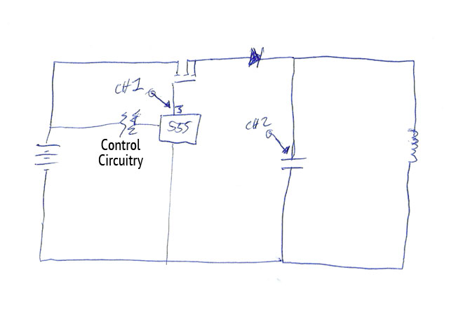
The circuit described involves a MOSFET driving a tank circuit, which is a resonant circuit typically used in applications such as RF transmission or signal generation. The top channel's signal to the gate of the MOSFET controls the switching action, allowing current to flow through the tank circuit when the MOSFET is turned on.
The tank circuit comprises a large coil, which is likely an inductor, and a capacitor of 5µF. The coil's substantial size, combined with its ferrite core, suggests that it is designed to achieve a specific inductance, which, in conjunction with the capacitor, sets the resonant frequency of the circuit near 100 Hz. This frequency indicates that the circuit is likely intended for low-frequency applications, possibly in audio or low-power RF domains.
The bottom channel indicates the connection of the MOSFET source to the positive side of the tank capacitor. This configuration is typical in circuits where the MOSFET is used as a switch to control the energy stored in the tank circuit. When the MOSFET is turned off, the energy in the tank circuit can lead to oscillations, which are characteristic of resonant circuits.
The observed low voltage delay after the input signal is turned off and prior to the onset of oscillation could be attributed to several factors. One possibility is the inherent capacitance and inductance within the circuit, which can introduce a delay due to the time constants associated with charging and discharging. Additionally, the MOSFET's characteristics, such as gate charge and output capacitance, may also contribute to this delay.
Troubleshooting this phenomenon may involve measuring the gate voltage and the output voltage of the MOSFET to analyze the timing relationships. It may also be beneficial to examine the circuit layout for potential parasitic inductances and capacitances that could be influencing the performance. Understanding these dynamics is crucial for optimizing the circuit's response and achieving the desired oscillation characteristics.The top channel is my signal to the gate of a mosfet. The mosfet is driving a tank circuit that contains a large coil wrapped on ferrite with a 5uF capacitor. Thecoil is large enough that the frequency is near 100Hz. The bottom channel shows the positive side of the tank capacitor where the mosfet source is connected to drive the circuit.
What I`m confused as heck about is the low voltage delay after the input turns off and before the initial oscillation begins. I don`t recall ever running into something like this before. I`ve traced my circuit leads and double checked everything and I just don`t know what`s going on. Anyone else ever seen something like this in a tank circuit 🔗 External reference
Related Circuits
Without the specified delay, the circuit could malfunction or even sustain damage. A capacitor, which is a crucial component of the circuit, is positioned at the other end of the base resistor rather than directly connected to the base...
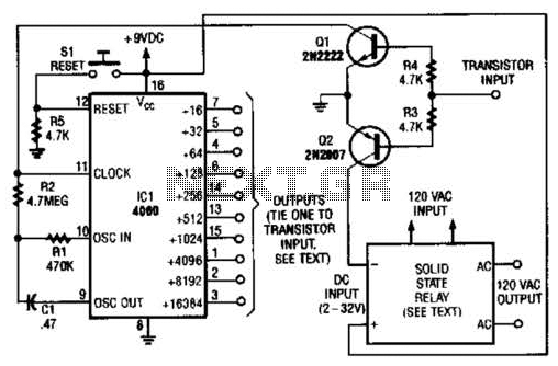
A long-duration timer can be easily constructed using a 4060 CMOS binary divider along with its integrated clock oscillator. The solid-state relay can be selected based on the specific application requirements and may be substituted with a mechanical relay...

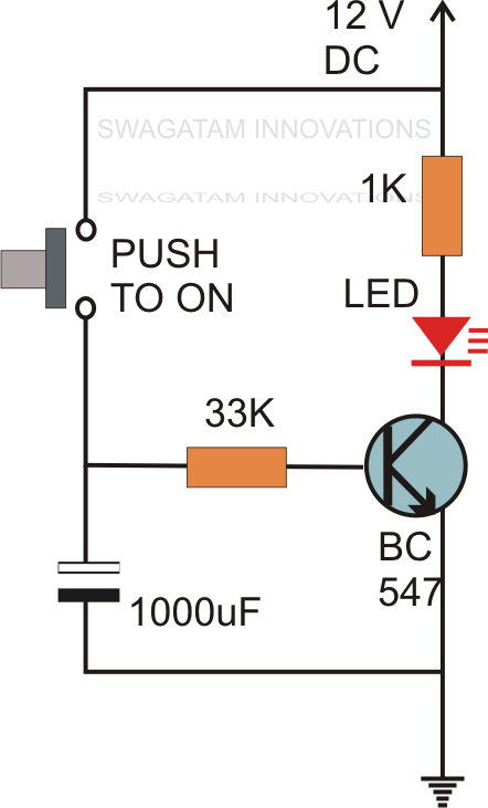
This is a simple touch switch circuit where the 555 timer is configured as a one-shot multivibrator triggered by touching the touch terminal. In monostable mode, the timer generates a fixed pulse of approximately 4 seconds whenever the trigger...
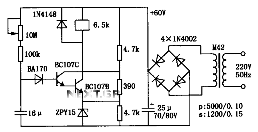
The circuit is a relay delay pull transistor configuration. Initially, when powered, the 16 µF capacitor has a voltage of zero, resulting in both transistors being off, and the relay remains inactive. As the 16 µF capacitor charges over...
Power line fluctuations and cut-offs can damage electrical appliances connected to the line, particularly domestic appliances such as refrigerators and air conditioners. When a refrigerator operates at low voltage, excessive current flows through the motor, leading to overheating and...
The delay circuit utilizes the Mitsubishi M65830 Digital Delay chip, as illustrated in Figure 1. This chip has been in use for some time and is known for its simplicity and effectiveness, particularly when a fixed delay is sufficient....
Warning: include(partials/cookie-banner.php): Failed to open stream: Permission denied in /var/www/html/nextgr/view-circuit.php on line 713
Warning: include(): Failed opening 'partials/cookie-banner.php' for inclusion (include_path='.:/usr/share/php') in /var/www/html/nextgr/view-circuit.php on line 713