
darklight sensor using transistor
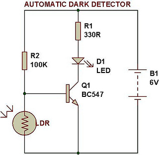
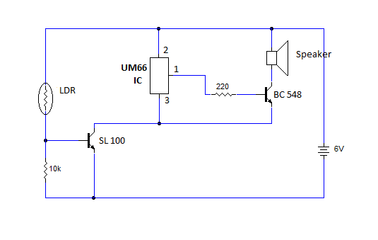
This circuit operates based on the principle of light-dependent resistors (LDRs), which change their resistance according to the ambient light level. In bright conditions, the resistance of the LDR decreases, allowing current to flow through the circuit. When the light level drops below a certain threshold, the resistance increases, triggering the activation of LED D1.
The circuit comprises an LDR connected in a voltage divider configuration with a fixed resistor. The output from this configuration is fed into a comparator circuit, which compares the voltage across the LDR with a reference voltage set by a potentiometer. When the voltage across the LDR exceeds the reference voltage, the comparator output changes state, activating the LED.
To enhance functionality, the circuit includes a variable resistor (VR1-10K), which allows for fine-tuning of the sensitivity. By adjusting this resistor, users can set the desired light level at which the LED will turn on or off. This feature makes the circuit versatile for various applications, such as automatic street lighting or garden lights that activate at dusk and deactivate at dawn.
In summary, this automatic dark detector and light detector circuit is a practical implementation of light sensing technology, providing an efficient solution for automatic lighting control based on ambient light conditions.Automatic dark detector senses darkness. As the light level decreases and LDR meets the maximum threshold resistance, the circuit automatically switches on the LED D1. A light detector senses light. As the light level increases and LDR meets the lowest threshold resistance, the circuit automatically turns on the LED D1.
We can adjust the sensitivi ty using the preset VR1-10K. 🔗 External reference
Related Circuits
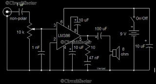
This is a simple low-power audio amplifier circuit capable of producing a power output of 1W. The mono amplifier circuit is built around the LM386 integrated circuit, which operates effectively at low voltages, even below 9V. This low-voltage amplifier...
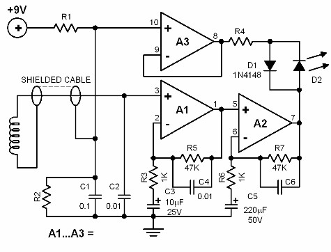
This electronic device functions similarly to a metal detector but has a unique capability: it detects live electrical wires. This gadget is particularly beneficial for electricians engaged in repair or renovation tasks. The ability to locate hidden wires significantly...
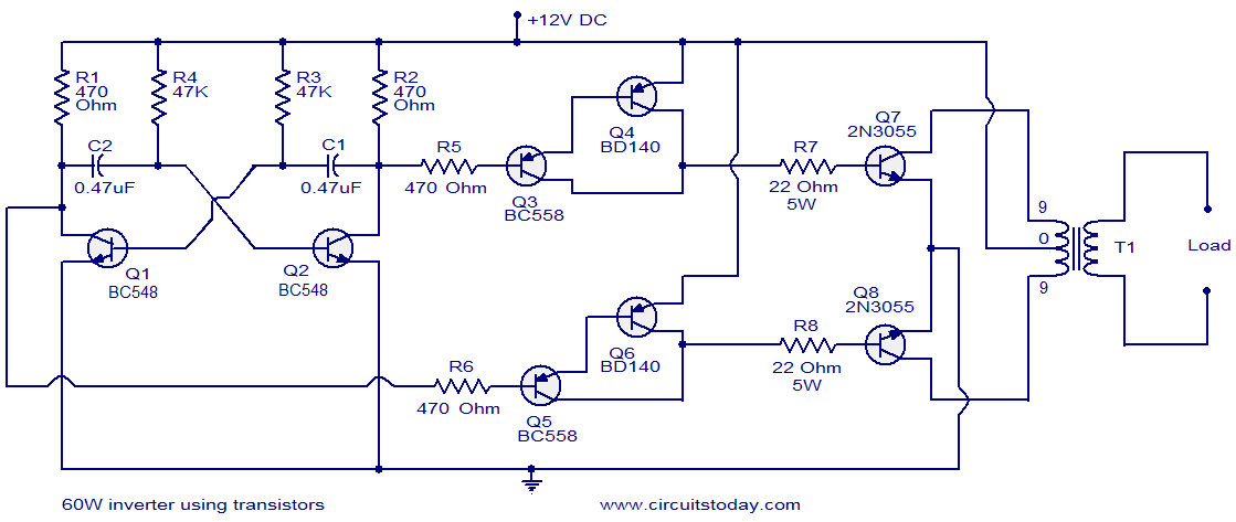
This circuit diagram illustrates a fully transistorized inverter capable of driving loads of up to 60W. Transistors Q1 and Q2 create a 50Hz astable multivibrator. The output from the collector of Q2 connects to the input of a Darlington...
This article provides instructions for creating a light-sensitive morning alarm circuit. The circuit utilizes an LDR (Light Dependent Resistor) or photoresistor to detect morning light, which triggers the alarm section. When light is detected, the circuit produces a melodious...
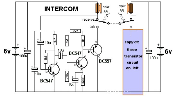
The key to avoiding instability (motor-boating) in a high-gain circuit is to power the speaker using a separate power supply. This circuit design allows for the connection of one or two additional stations. It is recommended to construct the...

If you require a small lamp that flashes for general use, there are numerous options available. Today, three lamp flasher circuits will be presented. The three lamp flasher circuits can be designed using different components and configurations, each offering unique...