
Data Recorder
The Data Recorder (A3007) is a sophisticated device designed for decoding and recording SCT messages, operating within the LWDAQ framework. The device's architecture is centered around a demodulator, which is critical for converting RF signals into usable data. The 512-KByte memory capacity allows for substantial storage of recorded messages, enabling extensive data collection during experiments or monitoring sessions.
The A3007D model, specifically, is engineered for optimal performance with its modified discriminator filter, enhancing the ability to accurately decode messages even in environments with weak signals. The integration of auxiliary power sockets facilitates the operation of RF circuits, ensuring that the device can function effectively in various applications. The programming of the logic chip through the 8-way SIP connector allows for flexibility and updates as needed.
Indicator lamps serve as a real-time status check for the device's operation, providing immediate feedback on the system's functionality. The placement of the BNC plug at the bottom center of the device is a strategic design choice, allowing for easy access to the demodulated SCT signal, which is essential for the proper functioning of the device.
In terms of reliability, the A3007D has undergone rigorous testing and revisions, particularly with respect to its firmware. The transition from earlier versions, which experienced issues such as timing inaccuracies and corrupted data, to the current iteration reflects a commitment to enhancing performance and functionality. The resolution of issues related to corrosion and signal integrity further underscores the device's robustness and reliability.
Overall, the A3007 Data Recorder represents a significant advancement in the field of electronic data collection, providing researchers and engineers with a reliable tool for capturing and analyzing critical data from subcutaneous transmitters. The ongoing improvements and meticulous attention to detail in the design and functionality of the device ensure its relevance and efficacy in contemporary applications.The Data Recorder (A3007) is a LWDAQ Device that decodes and recordes subcutaneous transmitter ( SCT ) messagess. The A3007 takes the signal generated by a demodulator such as the Demodulating Amplifier ( A3017 ) and determines when this signal contains a valid SCT message sequence.
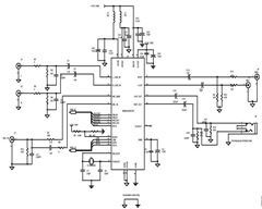
It stores messages in its 512-KByte memory and makes them availab le to the LWDAQ. Figure: An A3007D in A3018C Enclosure. Auxilliary power sockets on top and right side are used to power RF circuits. The square logic chip is programmed throug the 8-way SIP connector. The RAM is on the right. Four indicator lamps are on the left, with the LWDAQ device socket. The discriminator comparator and RC circuits are on the bottom center, near the BNC plug that brings in the demodulated SCT signal. The A3007 is used in the Data Receiver ( A3018 ). The A3007A and A3007B were used in the Data Receiver ( A3010 ). These versions are obsolete. The A3007A was unreliable because it used a ring oscillator to generate timing for the upload to the LWDAQ driver.
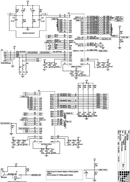
The A3007B was equipped with a 40-MHz crystal oscillator piggy-backed onto the logic chip. Both the A and B versions are obsolete. We added a 40-MHz oscillator to the A3007C, which is shown in page two of the schematic. The A3007D has a modified discriminator filter on its input, which gives superior message decoding. The A3007E fixes a severe bug in the firmware that generated bad messages in the presence of interference. S3007_2 : Second page of circuit diagram showing data clock oscillator, power distribution connectors, and indicator lamp logic.
The A3007C used 10nF for C10, but in the A3007D we reduce C10 to 1nF so we can see poor reception as a reduction in intensity of D1. The A3007C used different values for the discriminator: R2=0 ©, C4=1nF, C8=0nF, and R3=51 ©. In the A3007D we return to the values we used in the A3007A and A3007B, which give better isolation of the 5 MHz bit signal for better performance with weak signals.
See the Data Receiver manual for more details and here for the discriminator`s frequency response, which we discuss here. [11-JAN-13] The A3007D in A3018C assembly P0193 is giving currupted data. We investigate. It turns out that the connection between U7-78 and U6-38, which is the A14 connection to the RAM, is broken.
We find that the break is somewhere between the U7-78 pad on the top side and the bottom side of a via under U7. The vias under U7 and U6 both are dull and in places have copper showing through the solder coating. We suspect that we left corrosive water-soluble flux beneat these chips and as a result, after five years, one of the tracks has been eaten through entirely.
We removed both chips during the course of our investigation and cleaned the board thoroughly. We added a wire link from U7-78 to U6-38 and the board functions perfectly. [11-JAN-13] We enhance the A3007 firmware with diagnostic options and correct what we perceive to be a couple of errors. The result is firmware V06. But the new code, despite its promise, produces a TCPIP timeout error every few hundred seconds, while Version 4 does not.
So Version 6 is not ready for production. [13-JAN-13] We go through V06 comparing it to V04 and discover a combinatorial assignation for TBL when we should have a register assignation. For some reason this does not give us a warning or error message as it is supposed to. We correct the error and try V06 again. After an hour of recording, we see no errors, so we deem it ready for use in our demonstration Data Receiver.
[11-FEB-13] We receive Data Receiver (A3018C) number Q0128 from ION. It is delivering severely corrupted data. We inspect the bottom side of the board. We see plenty of acqueous flux residue plugging the vias beneath U7. The via plating is gray. We check the connection between U7-78 and U6-38 and find it intact. But U7-80 to U6-40 is broken. We remove U7 and find the corroded vias shown below. 🔗 External reference
Related Circuits
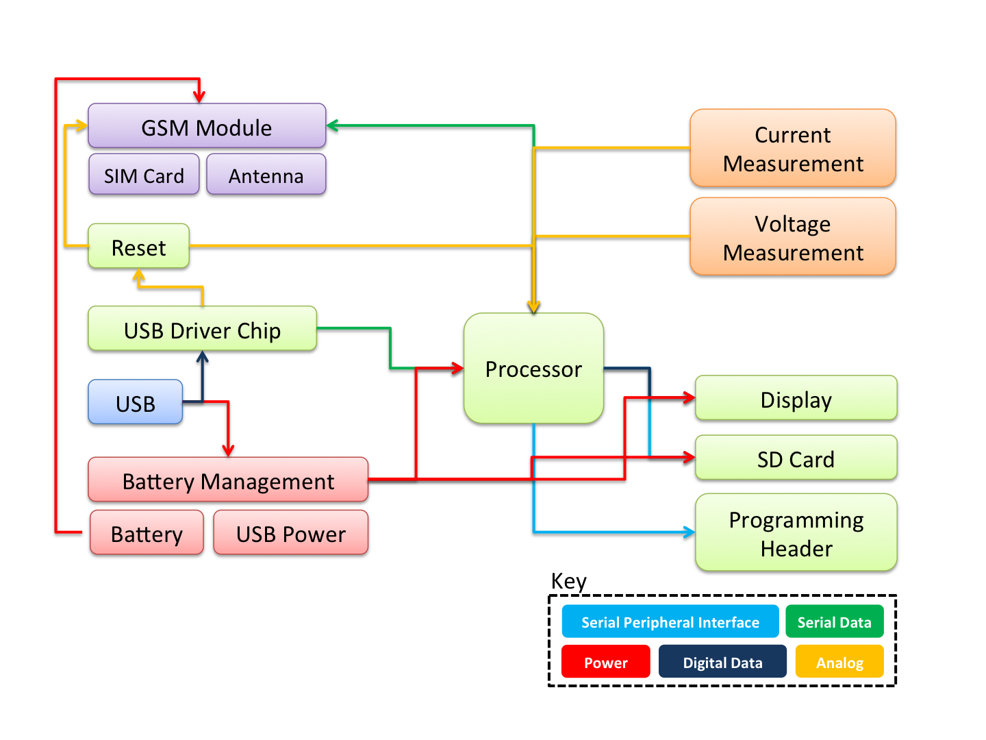
Datagoo is based on the ATMEGA328P microcontroller, widely used by hobbyists in various Arduino projects. It can be programmed via any computer with a USB port when paired with an FTDI FT232RL USB-Serial circuit. Cost-effectiveness and simplicity were prioritized...
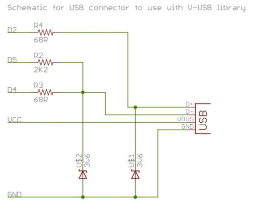
To successfully complete this project, it is necessary to construct the circuit as illustrated or as previously demonstrated. While the construction process is straightforward, any errors may prevent the V-USB software from functioning properly, potentially resulting in project failure....
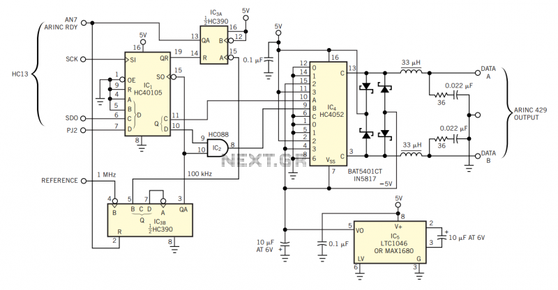
The physical transmission medium for the 429 standard is 78Ω shielded, twisted-pair cable that uses a complementary, differential bipolar RZ (return-to-zero) waveform. The voltages are the net differentials that the biphase drive develops: For example, the differential is 10V...
A typical circuit for applications such as mobile phones, MP3 players, and portable electronics utilizing the SSM2602 Low Power Audio Codec is provided in the SSM2602 Applications Circuit Schematic. The SSM2602 Low Power Audio Codec is designed for high-performance audio...
This section describes an experimental low power, low bandwidth data signaling system that was initially made to operate at 55 MHz (television channel 2 in the U.S.). Before operating a radio transmitter, find out what kind of transmitter operation,...
Control your instrument with a 4x20 LCD display and a 4x5 keypad designed for front panel feedback and control. The circuit involves an interface that utilizes a 4x20 LCD display and a 4x5 keypad, providing an effective means of user...