
DC Coupled Transistor Amplifier
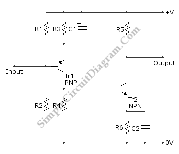
The directly coupled amplifier circuit utilizes both NPN and PNP transistors to achieve its amplification. In this configuration, the output of one transistor directly connects to the input of the next stage, ensuring that the DC level is preserved throughout the amplification process. This design is particularly advantageous for applications requiring the amplification of low-frequency signals or DC levels, such as sensor outputs or audio signals.
In a typical implementation, the NPN transistor serves as the first stage of amplification, where it receives the input signal and amplifies it. The output from the NPN transistor is then fed into the base of the PNP transistor. This cascaded arrangement allows for higher gain while maintaining stability and linearity in the output. Biasing resistors are used to set the operating point of both transistors, ensuring they remain in the active region for optimal performance.
The circuit may also include coupling capacitors at the input and output stages to block any unwanted AC components while allowing the DC signals to pass. The power supply for the circuit should be adequately decoupled to prevent noise from affecting the performance of the amplifier. Overall, this configuration is effective for applications where DC signal fidelity is crucial, providing a reliable method for signal amplification.This is a The Directly (DC) Coupled Amplifier circuit. This circuit is built from NPN transistor and PNP transistor. This circuit is used to amplify a DC.. 🔗 External reference
Related Circuits
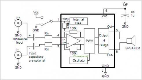
A current-sense amplifier is utilized to enhance the performance of the LM1875 current-mode amplifier circuit, as depicted in Figure 5-20. The resistor R3 and the series resistance of the speaker contribute to the current flowing through R3. This current...
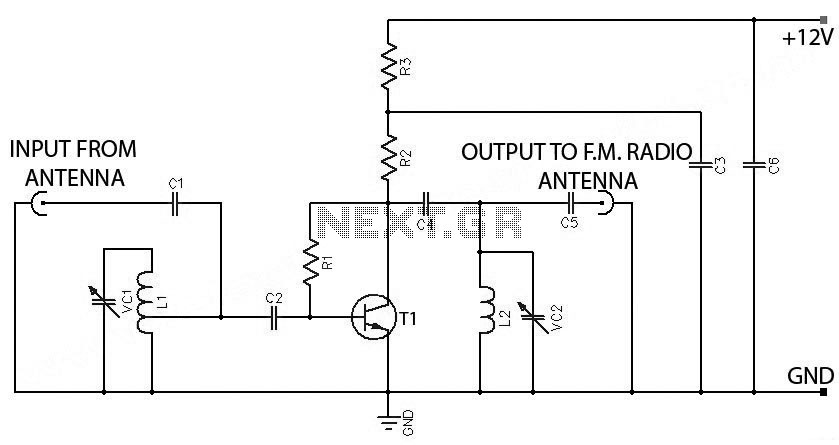
FM Booster, Active FM Antenna Amplifier. This FM booster can be used to listen to programs from distant FM stations clearly. The circuit comprises a common-emitter tuned RF preamplifier wired around VHF/UHF transistor 2SC2570. The FM booster circuit is designed...
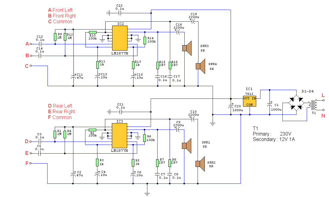
This is a four-channel amplifier designed for use with quadraphonic equipment, such as a Sound Blaster Live card. There is no volume control; audio levels are managed directly by the sound card. The construction is straightforward and suitable for...

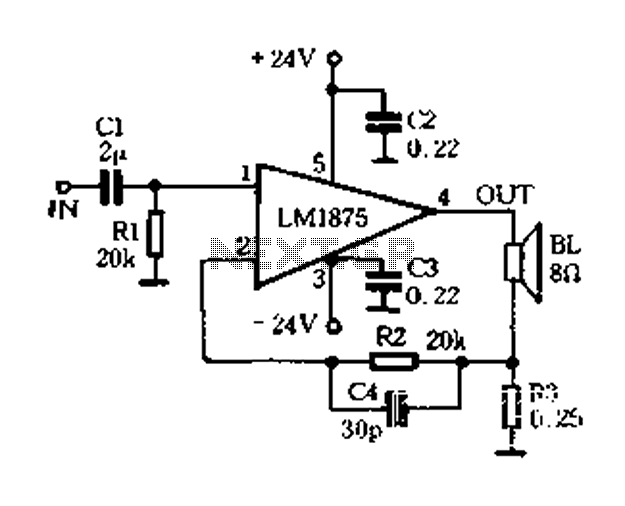
This is a standard amplifier based on LM 1875. It can deliver 20 W, with an 8 Ω speaker and 60V power supply even 30 W. The capacitors C4 and C5 should preferably be as close to the IC down....
Stationary - MOPLL & Silicon Tuner TUA6020 2 Band TV Tuner Mixer-Oscillator-PLL with balanced IF-Amplifier. The TUA6020 device integrates a digitally programmable Phase Locked Loop (PLL) with a mixer-oscillator block that includes two balanced mixers and oscillators suitable for...
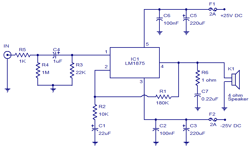
This weblog focuses on electronic circuit schematics, PCB design, DIY kits, and electronic project diagrams. The featured project is a 20W audio amplifier circuit based on the LM1875 audio amplifier IC from National Semiconductors. With a 25V power supply,...
Warning: include(partials/cookie-banner.php): Failed to open stream: Permission denied in /var/www/html/nextgr/view-circuit.php on line 713
Warning: include(): Failed opening 'partials/cookie-banner.php' for inclusion (include_path='.:/usr/share/php') in /var/www/html/nextgr/view-circuit.php on line 713