
dc motor 12v speed controller circuit
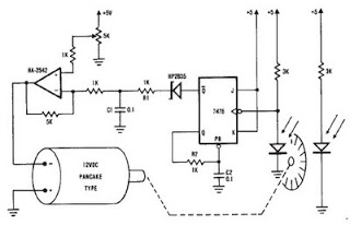
The described encoder circuit for a DC motor utilizes the HA-2542 operational amplifier to achieve effective speed control. The core functionality revolves around the position encoder, which outputs a series of pulses corresponding to the motor's rotational position. Each pulse indicates a specific increment of movement, allowing for precise speed measurement and control.
In the configuration, capacitor C1 serves as a charge storage component, integrating the pulse signals from the encoder. The reference voltage generated is directly proportional to the motor's speed, thus enabling real-time feedback for the control system. The HA-2542 operational amplifier is configured in a differential mode, where the inverting input receives the integrated pulse signal, while the non-inverting input is set to a predetermined voltage that signifies the target speed. This setup facilitates the comparison of actual speed against the desired speed.
If a discrepancy exists between the actual speed (inverting input) and the desired speed (non-inverting input), the operational amplifier outputs a corrective signal. This signal adjusts the power supplied to the DC motor, ensuring that it accelerates or decelerates to match the set speed. The simplicity of the circuit design, with minimal external components, enhances its reliability and ease of implementation.
The limitation mentioned regarding the encoder wheel can be mitigated by incorporating a pulley system. By attaching a pulley to the encoder wheel, the motor can be connected to another device via a belt. This allows the speed control system to influence the operation of additional machinery, effectively expanding the circuit's application beyond a single motor. This versatility makes the encoder circuit suitable for various automation and control projects, where precise speed regulation is essential.A very simple encoder circuit for a dc motor can be constructed using this circuit diagram. As you can see in the circuit diagram, the system shown consists of the HA-2542, a small 12-Vdc motor, and a position encoder. During operation, the encoder causes a series of constant-width" pulses to charge CI. The integrated pulses develop a reference voltage, which is propor £ional to motor speed and is applied to the inverting input of HA-2542, The noninverting input is held at a constant voltage, which represents the desired motor speed. A difference between these two inputs will send a corrected drive signal to the motor, which completes the speed control system loop.
As you can see the circuit requires few external components, but because of the encoder wheel it has a limitations of use. If you put a pulley under the encoder wheel you can command the speed of other device, by connecting the (motor and other device ) using a belt
🔗 External reference
Related Circuits
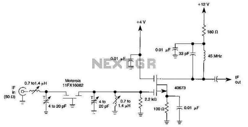
A 40673 dual-gate MOSFET is matched to a crystal filter operating at 45 MHz. The filter impedance is approximately 2 kΩ. The +4 V source can be adjusted to control the gain, ranging from +4 V to -4 V. The...
The chip in the center with small bullet holes is likely proprietary. It is possible to salvage a few components from it, although understanding the circuit is not necessary for this purpose. Additionally, it is confirmed that the device...
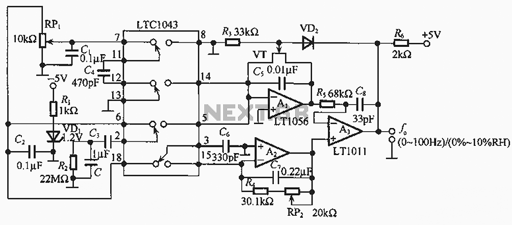
The humidity/frequency conversion circuit operates similarly to the previously mentioned humidity sensors. At a humidity level of 76%, the equivalent capacitance is 500 pF, with a capacitive relative humidity variation rate of +1.7 pF/%. The circuit includes an integrating...
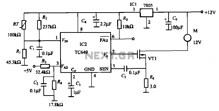
A motor is a heating device that can overheat, often due to accidents or overloads caused by excessive coil winding temperatures. The TC649 motor overheating protection and drive circuit, depicted in FIG. 1-9, utilizes an NTC thermistor (RT) positioned...
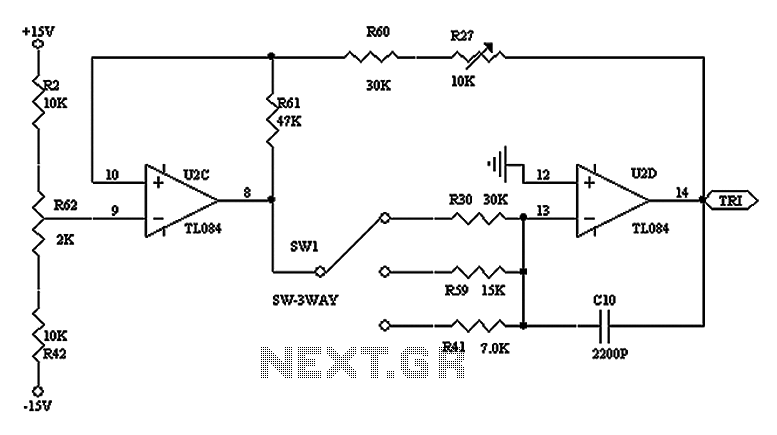
The triangular wave circuit consists of two operational amplifiers (OPs). R62 serves as the offset adjustment, while R27 is utilized for peak adjustment. A switch is included to select different resistances, allowing for the generation of triangular waves at...
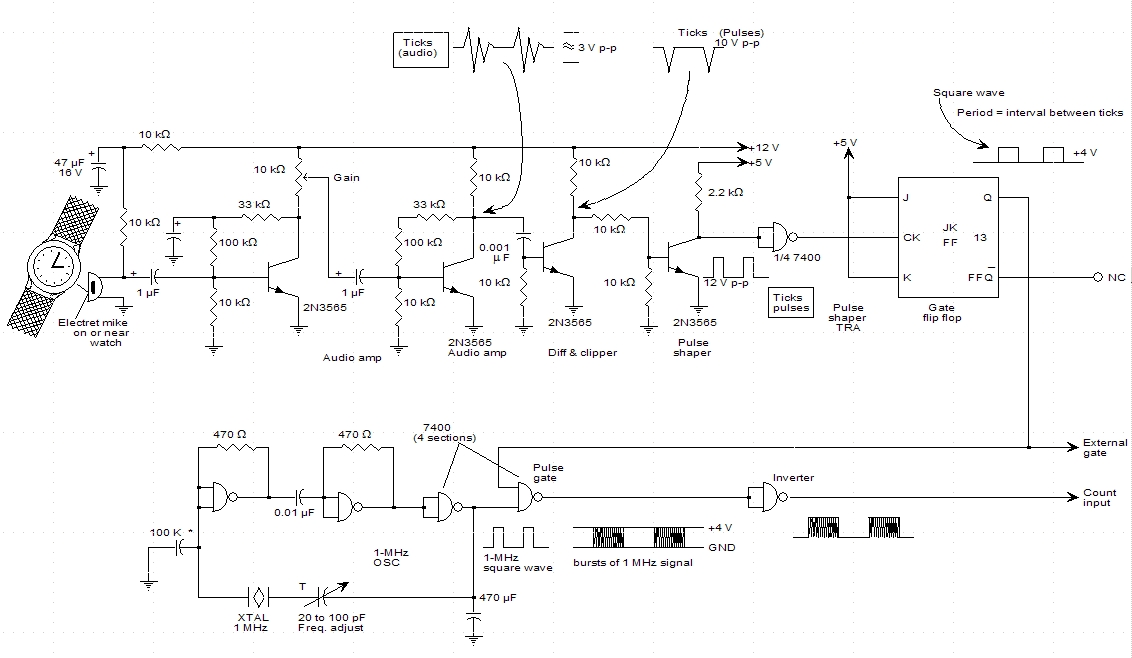
A schematic for a watch timer was found in a hobby electronics book. The circuit adapts a frequency counter to measure intervals. Watch ticks are clipped, shaped, and formed into a square wave. This square wave is utilized to...