
Dc-motor-drive-with-fixed-speed-control
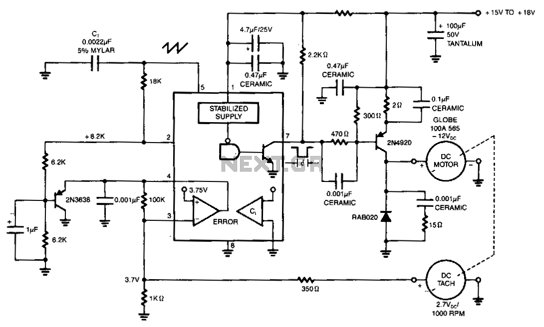
The NE5561 provides pulse-proportional drive and speed control based on DC tachometer feedback. This simple switching circuit consists of a 2N4920 PNP transistor with a commutation diode, which is used to deliver programmed pulse energy to the motor. A frequency of approximately 20 kHz is employed to eliminate audio noise. The DC tachometer delivers 2.7 V per 1000 RPM. Negative feedback occurs when this voltage is applied to the error amplifier of the NE5561. The duty cycle varies directly with load torque demand. The no-load current is 0.3 A, and the full load current is 0.6 A.
The NE5561 integrated circuit is utilized in applications requiring precise control of motor speed and torque through feedback mechanisms. The circuit design incorporates a 2N4920 PNP transistor, which functions as a switch to regulate the power delivered to the motor. The inclusion of a commutation diode is critical as it protects the circuit from voltage spikes generated when the motor is switched off, ensuring stable operation and prolonging the lifespan of the components.
The operational frequency of approximately 20 kHz is chosen to avoid audible noise, which can be a significant issue in motor control applications. By modulating the pulse width of the signal delivered to the motor, the circuit can adjust the power output effectively, allowing for smooth transitions in speed and torque.
The feedback mechanism is facilitated by the DC tachometer, which produces a voltage proportional to the motor's speed. Specifically, it generates 2.7 V for every 1000 RPM. This voltage is fed back into the error amplifier of the NE5561, where it is compared to a reference voltage. The resulting error signal is used to adjust the duty cycle of the output pulse, ensuring that the motor operates at the desired speed and responds dynamically to changes in load torque demand.
Under no-load conditions, the current drawn by the motor is 0.3 A, while under full load, the current increases to 0.6 A. This variation in current is indicative of the motor's operational efficiency and the effectiveness of the control circuit in adapting to different load conditions. By analyzing the current draw alongside the feedback voltage, the circuit can maintain optimal performance across various operational scenarios.
Overall, this configuration provides a robust solution for applications requiring reliable motor control with precise speed and torque adjustments, leveraging the feedback from the DC tachometer to enhance performance and efficiency.The NE5561 provides pulse-proportional drive and speed control based on de tachometer feedback. This simple switching circuit consists of transistor 2N4920 pnp with a commutation diode used to deliver programmed pulse energy to the motor. A frequency of approximately 20 kHz is used to eliminate audio noise. The de tach delivers 2.7 V/1000 RPM. Negative feedback occurs when this voltage is applied to the error amplifier of the NE5561. The duty cycle varies directly with load torque demand. The no-load current is = 0.3 A and full load is 0.6 A. 🔗 External reference