
DC motor speed control
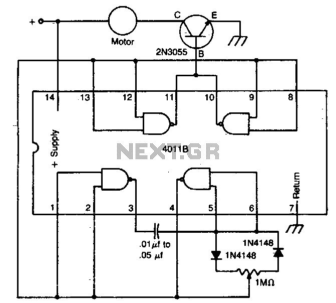
The circuit operates by leveraging the characteristics of the 4011 CMOS NAND gate, which is configured to generate a square wave signal. This signal, when passed through the diodes, allows for the modulation of the voltage applied to the motor. The diodes ensure that the current flows in one direction, preventing back EMF from the motor from affecting the circuit's operation. The NPN power transistor acts as a switch, controlled by the output of the NAND gate, allowing for the rapid on-off cycling that defines pulse width modulation (PWM).
The speed control mechanism can be implemented using a variable resistor or a potentiometer, which adjusts the duty cycle of the PWM signal. As the duty cycle increases, the average voltage supplied to the motor also increases, resulting in higher speeds. Conversely, reducing the duty cycle lowers the average voltage, allowing for finer control at lower speeds. This method is particularly advantageous for applications requiring precise speed adjustments, such as in robotics or conveyor systems.
At low speeds, the motor receives short bursts of power, which keeps it moving without overheating. The design ensures that the motor is not subjected to continuous high voltage, which could lead to thermal issues. As the speed increases, the motor's operation becomes more stable, resembling its behavior in a direct connection to a DC source. This circuit is beneficial for applications where energy efficiency and precise control over motor speed are critical, as it minimizes wasted power while maximizing operational effectiveness.The circuit uses a 4011 CMOS NAND gate, a pair of diodes and an NPN power transistor to provide a variable duty-cycle dc source. Adjusting the speed control varies the average voltage applied to the motor. The peak voltage, however, is not changed. This pulse power is effective at very low speeds, constantly kicking the motor along At higher speeds, the motor behaves in a nearly normal manner. 🔗 External reference
Related Circuits
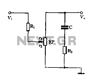
Figure 1-87 illustrates an effective loudness volume control circuit that employs a standard potentiometer. The components used are minimal, yet the performance is notably impressive. The operation principle is as follows: when the internal impedance of the source is...
Car and Motorcycle Battery Tester Circuit. Going camping today often requires bringing various electronic devices for daily activities or entertainment. Typically, a charged lead-acid battery and a power source are essential. The Car and Motorcycle Battery Tester Circuit is designed...
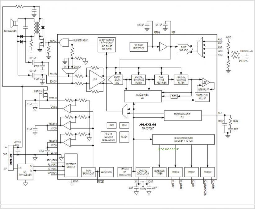
The MC33411 900 MHz Analog Cordless Phone Baseband system is designed to meet the specifications of a 900 MHz Analog cordless telephone system. It includes three Phase-Locked Loops (PLLs). Two of these PLLs are intended for use with external...
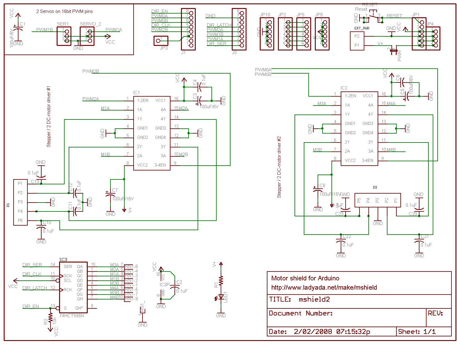
Arduino is an open-source electronics prototyping platform that features flexible and user-friendly hardware and software. It is designed for artists, designers, hobbyists, and anyone interested in creating interactive objects or environments. Arduino can sense the environment by receiving input...
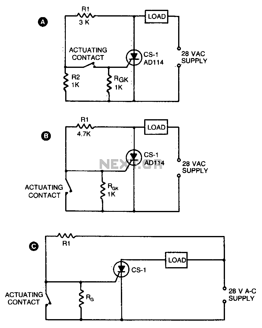
Two simple arrangements for resistive loads are shown in A and B. The circuit in A will provide load power when the actuating contact is closed, and no power when the contact is open. B provides the reverse of...
I found some similar circuits but aren't good enough for me. Some circuits measure the water's resistance to determine the level. That is dangerous for drinking water (contamination) or explosive liquids because electricity is in contact with water. The...