
Dc static switch
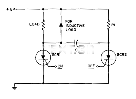
This static SCR switch circuit utilizes two silicon-controlled rectifiers (SCRs) to control the flow of current in a DC circuit. The primary operational mechanism relies on the gate control of SCR1, which allows for the initiation of current flow to the load when a low-power signal is applied. The triggering of SCR1 is crucial for the circuit's operation, as it enables the load to receive voltage.
Once SCR1 is activated, capacitor C begins to charge through resistor R1. The charging process causes the voltage across capacitor C to increase, resulting in a positive charge on the right plate relative to the left plate. The charging time constant is determined by the resistance value of R1 and the capacitance of C, influencing the rate at which the capacitor charges.
The role of SCR2 becomes significant when it is triggered. Upon activation, SCR2 connects capacitor C across SCR1, creating a reverse voltage condition. This reverse biasing momentarily disrupts the conduction path of SCR1, effectively turning it off. This action is contingent upon the condition that the gate signals are not applied to both SCRs simultaneously, which would otherwise maintain SCR1 in a conductive state.
As capacitor C charges, the current flowing through the load decreases exponentially. This behavior is characteristic of RC charging circuits, where the current diminishes as the capacitor approaches its maximum charge. The gradual reduction in current ensures a smooth transition to zero load current, which can be beneficial in applications where abrupt changes in current could cause issues.
Overall, this circuit provides a reliable means of controlling DC loads through the use of SCR technology, allowing for efficient switching and current management. Proper selection of component values for R1 and C is essential to achieve the desired timing and performance characteristics of the circuit.This circuit is a static SCR switch for use in a dc circuit. When a low power signal is applied to the gate of SCR1, this SCR is triggered and voltage is applied to the load. The right hand plate of C charges positively with respect to the left hand plate through Rl. When SCR2 is triggered on, capacitor C is connected across SCR1, so that this SCR is momentarily reverse biased between anode and cathode.
This reverse voltage turns SCR1 off provided the gate signal is not applied simultaneously to both gates. The current through the load will decrease to zero in an exponential fashion as C becomes charged. 🔗 External reference
Related Circuits
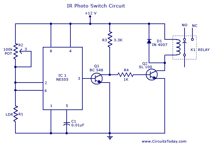
A simple photo switch circuit using an NE 555 IC with a diagram and schematic. This photo switch activates a relay when light intensity crosses a specified limit. It is a light sensor circuit suitable for home and industrial...
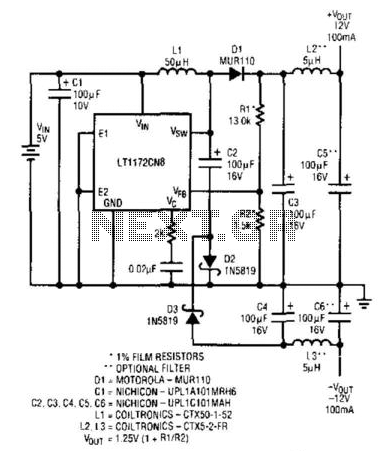
An LT1172 generates positive and negative voltages from a 5-V input. The LT1172 is configured as a step-up converter. To generate the negative output, a charge pump is used. C2 is charged by the inductor when D2 is forward-biased...
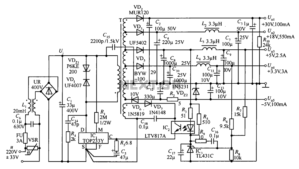
A 35W switching power supply circuit designed for a set-top box output is depicted in Figure 5. It features five distinct voltage outputs: Uo1 (+30V, 100mA), Uo2 (+18V, 550mA), Uo3 (+5V, 2.5A), Uo4 (+3.3V, 3A), and Uo5 (-5V, 100mA)....
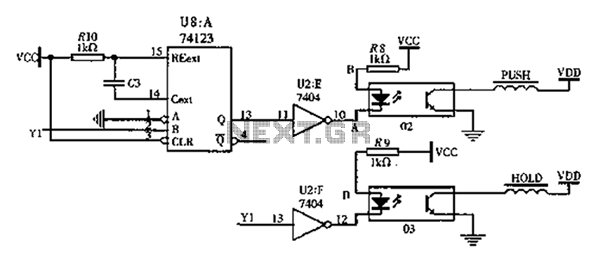
The FIG switching solenoid driver circuit utilizes the 74123 device chip (U8) and solid-state relays (02, 03). The switching electromagnet coil is referred to as the PUSH coil, while the HOL is maintained at a power supply voltage (VDD)...
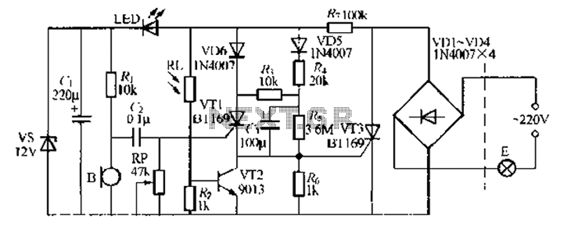
A relatively simple circuit for controlling a stair walkway light with a delay feature. The circuit has a drawback in that the voice activation is somewhat less sensitive, making it sometimes difficult to trigger with general conversation. However, it...

This simple circuit shown in the schematic diagram activates the switch using sound. This circuit can be used for various applications, such as automatic switching. The circuit utilizes a sound sensor, which is typically a microphone or a piezoelectric sensor,...
Warning: include(partials/cookie-banner.php): Failed to open stream: Permission denied in /var/www/html/nextgr/view-circuit.php on line 713
Warning: include(): Failed opening 'partials/cookie-banner.php' for inclusion (include_path='.:/usr/share/php') in /var/www/html/nextgr/view-circuit.php on line 713